Saturday, 5 January 2013

Orientation of Cutter Heads


In addition to the alignment of the cutter, you need to be sure you are moving the cutter forward in the way it was designed. If you look at the cutter from the side you will see two things. The most obvious one is that the angles of the cutaway on the head are shallower at the front and steeper at the back. In addition if you look carefully, the axel for the wheel is slightly forward of the centre line of the whole cutter.

Cutters aligned to score to the left


So it does not matter where the fixing screw on the head is. It may be at the front or at the back. What matters is the cutaway at the back which allows the cutter to be used with a shallower angle, than if reversed. This is most obvious on wide cutter heads.

Cutters arranged to score to the right


Sunday, 30 December 2012

Repair of a Plastic Barrel Cutter


Generally, there are two parts that can break or be damaged – the wheel and the barrel.

Wheel
If the wheel is damaged or worn, you can replace the head. When considering that, look at the cost of the head and consider whether the small cost difference indicates you should buy a new cutter instead.

The most common damage is a flat spot on the wheel. You can check for this, immediately after dropping the cutter, by lightly moving the cutter across a smooth piece of glass. If you hear a regular ticking sound, the wheel is probably “flat spotted” and will need to be replaced.

A worn wheel is more difficult to detect and is also much less likely to occur. I have been using some of my cutters for 15 years without any sign of being worn.

Plastic barrel
Sometimes the plastic barrel cracks or breaks. This will mean that the oil in the cutter will leak out. So you can consider continuing to use the cutter without oil, or by dipping the head in an oil soaked bit of cotton wool or similar material before each cut.

If the break is at the threaded end and you want to continue to use the ball at the end for tapping purposes, you can glue the barrel back together with an epoxy resin. Make sure the pieces are free from oil. Then glue and allow to cure. After curing, sand down any excess resin to make the cutter comfortable to handle.

Then for additional strength you can wrap with dental floss or extremely fine wire. Start below the glued area and go to the end of the break and back again. You could coat this wrapping with epoxy again both to secure the wrapping and to further increase the strength.

Another solution is to cut the cracked end off and re-thread the remainder. It makes the cutter a little shorter, but will continue to hold oil and give good service.

Or, you could buy another cutter.


Tuesday, 25 December 2012

Gas Fired Kilns


Installing a Gas Fired Kiln

There are a number of considerations about the location of a gas kiln.

Air exchange
The kiln should be placed in an area where there is good air exchange. For a number of reasons, it is usually convenient to place the kiln near an outside wall – ventilation and canister storage are the two most important.

Ventilation
There should be a low level vent to the outside to allow air to rise for the use of the combusting gas. There needs to be high level vent for the gas to escape. Ideally a hood with powered extraction would be installed.

Space
As with any kiln, you need to have sufficient space around the kiln to avoid heating any flammable materials. In the case of a gas kiln you need to be careful to avoid storing any thing that might ignite above the kiln. You can put heat resistant materials around the kiln if desired.

Location and storage of gas canisters
The safest place to put the gas canisters is outside the building. This does mean going outside to turn the valve on the gas canister on and off. However this is the safest place, should any fire start in the building, because the fire brigade can find and remove it from the fire. This placing applies to both the in use canister and any other full or empty canisters.

Detectors
Finally, even with these precautions, you should install a carbon monoxide detector. Carbon monoxide has no smell and can overcome you very quickly. Even a few minutes of exposure can leave you feeling ill for days.  

Thursday, 20 December 2012

Paint and Cold Working

One of the difficult things in cold working is determining when it is time to move on to the next grit size.  You really cannot tell while the piece is wet, because the water disguises the minute scratches put into the glass by the grinding process.

After you have dried the piece, you can coat it with a white paint pen. It is not necessary to cover the piece completely in white pen.  The white marks will be taken away by the grinding to give evidence of where you have already ground the piece.


Piece prepared for the next stage of grinding

You must make sure the paint has completely dried, or it will wash off with the water used in the grinding.

I find I get best results from this "witness" by making the paint pen marks at right angles to the grinding direction.  When all traces of the paint have disappeared, you have thoroughly covered the piece with that grit size.  Being ever cautious, I tend to dry, paint and do a second pass at the same grit before going to the next finer grit.

Saturday, 15 December 2012

Cold Working Holes

If you have, or expose, holes while cold working a piece, you need to keep the glass waste from settling into them. Dry the piece and with a bar of hard soap rub over the area until the holes are filled with soap. Then polish off the excess with a cloth or paper towel. 

The filled hole in this piece is the white dot half way up on the right side


When finished cold working, you only need to wash out the soap, which is much easier than trying to get rid of powdered glass.


Based on comments from Cynthia Morgan, posting as Morganica

Monday, 10 December 2012

Diamond Quarries


Diamond quarry glazing appears to be simple. But because if its simplicity it must be both accurate and aesthetically pleasing. Diamond quarried windows look best if the individual pieces are taller than they are wide. The window also looks better if the lines forming the diamonds end in the corners of the window as it gives a pleasing wholeness.

Simple sketches to show the relative clutter of a 6x6 and a 4x4 pattern

You can try making a sketch and trying various options of numbers and angles. By this simple exercise, you can determine the amount of clutter (how many lines vs. how much glass shows) produced by various combinations. It is important that the proportions of your sketch should be the same as the that of the window for which you are designing. This sketching process lets you try out various numbers of quarries along the bottom and sides quickly as the lines do not have to be accurate. Once you have decided on a size that looks good on the sketch you can count up the number of divisions on the horizontal and vertical lines. This can then be translated into approximate sizes on the full sized cartoon.


Begin with the cut line cartoon. This seems obvious, but until you have measured the window and given the glazing and border leads allowance you are unable to design a damond quarry glazed window that will have its lines meeting the corners in the finished window.


Drawing the diagonals


Begin the designing process by drawing two diagonal lines from the corners of the panel to ensure the lines will finish in the corners. This will also determine the centre of the panel and show you the slope of the diagonals. If you have not already determined the size of the diamond quarries, you can try out different sizes of diamonds by drawing parallel lines to the diagonals. 

Centre point determined, trial sizes of quarry, and the sides divided

When you have a size you like, you can determine the number of diamonds horizontally and vertically across the panel. You need to measure the width and height – point to point – of the test diamond and divide the lengths of sides to determine the number of quarries up and across the window. 

In this example of a small window (380 mm x 280 mm), the quarry is about 50mm wide and 65 mm high.  The exact sizes are not too important.  Divide the length of the base and side lines to determine the number of divisions.  In this example it is five on the base and six on the side. To get the exact dimensions for the quarries, you can use the no-calculation method of dividing a line. [link]

The divisions are extended to the opposite vertical or horizontal line to provide points from which to draw the diagonals.

Lef to right diagonal lines drawn
In this example feint lines were drawn up and down across the panel.  This provides a check that the diagonals remain accurate.

Remaining diagonals drawn  and confirmed by horizontal and vertical check lines


Sometimes, however, the corner to corner diagonals are too steep or too shallow to make pleasing diamonds. Diamond quarries generally have slopes that fall in the range of 50 – 60 degrees (45 degrees gives square quarries and anything over 60 degrees gives such a narrow quarry as to be unplesant). In these cases you need to determine the approximate angle for the diamond shape before proceeding from the centre point. 

Centre found and test diagonal drawn
In this landscape format example the diamond is horizontal, but otherwise a suitable size, so the dimensions were taken of it to determine the number of quarries on each side.  In this case it was seven along the bottom and four along the side.

Normally a 55 degree angle is a suitable middle range slope for diamonds, so you can start with that to determine what number of pieces vertically and horizontally are appropriate.  

After marking off the equal number of spaces, you can determine which points will give you appropriately angled diagonals. 

Number of quarries determined and first diagonal drawn
It is important to count the same number of marks along on the base line as there are marks on the side.  You will see in the above picture - if you look closely - the effects of narrowing diamonds if you do not.

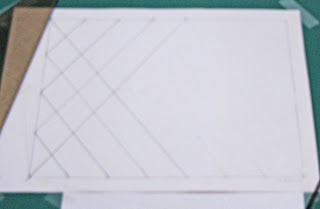
The second set of diagonals being added
After setting the diagonals on the first side and part of the base, continue with the parallel lines to the end.

Completed set of diagonals for a landscape window

This photo shows the completion of the diagonals.  It also shows the need for concentration.  I was interrupted and when I came back I drew a line from centre top to the next to last mark on the cartoon.  However, as you can see from the erasing, it should have been the corner mark that I drew to.  I point this out to emphasise how important it is to concentrate while doing this apparently simple task of joining the marks.

Wednesday, 5 December 2012

Dividing a Line

Dividing a Line into Equal Parts

There is a no-calculations method of dividing a line into equal parts. This describes how to divide a line into any number of equal parts without calculating and measuring the divisions.

The steps are:
Determine the number of divisions required across the base or perimeter line. Then draw a long line at a shallow angle to the line to be divided.

Angled line and dividers

Take a pair of dividers and open them to the approximate width of the individual division or piece.  In this example it was decided to have five divisions of about 50 mm.  The dividers are opened to 50 mm and marked off on the angled line from the corner the required number of times - in this case five.  

Then make a line from the last mark to the angled line to the end of the cartoon line with a right angle drawing square. 

Setting the angle

Place a long straight edge on the bottom of the drawing square and then mark the remaining divisions by maintaining the angle of the long straight edge while moving the drawing square from one mark to another. 

Moving the drawing square along the line and marking the base line


This process allows you to make equal divisions of a line without worrying about fractions of a centimetre or of an inch. It is simple and just as accurate as your skill in holding the straight edge steady while you run the drawing square along the edge and mark the base or vertical line.  In general it is more accurate than any calculations and measurements on the base or vertical lines.

Friday, 30 November 2012

Storing Moulds


Requirements

  • protection – some form of container is required to maintain the life of the mould. A container also prevents the kiln wash or other separator from being rubbed off.
  • ease of access – It should be easy to get to the moulds, especially as some can be heavy.
  • flat vs vertical – some like to store moulds in boxes vertically rather than horizontal with them stacked one above another.
  • In either case you need shelves of the right depth and height to store and support the moulds.
  • custom made vs bought in – Moulds you have purchased normally come in their own boxes which can be retained for storage for a number of years. You can also make light weight boxes either from old boxes or card cut to size and taped and glued together. More robust boxes can be made from thin plywood or thin pressed board.

Sunday, 25 November 2012

Quarry Glazing


For some reason that I have never learned, the regularly shaped pieces of glass that are leaded into a window are called quarries.  The derivation of the word relating to excavation comes from its middle English variant of medieval Latin quareria, from Old French quarriere, based on Latin quadrum 'a square'.   How it came to be applied to pieces of glass is unknown apparently.  However, in stained glass, "quarries" can relate to rectangles, diamonds, circles, etc., not only squares

These kinds of glazing are weak as there are long straight lines created with these designs. The best way of counteracting this weakness is to “weave” the lead joints within the panel combined with more frequent than usual glazing bars.

It may be wise to use a glazing bar at every second set of joints rather than merely consider the distance between bars.

Tuesday, 20 November 2012

Soldering corroded metals


Some investigation has shown that zinc corrodes more easily than lead (lead being a medium anodic and zinc a high anodic metal). Bronze, Copper and Brass are among the least easily corroded materials other than precious metals. Lead comes immediately after copper in the ease of corrosion.

The implication is that more easily corroded materials need more aggressive/abrasive cleaning before soldering and that their longevity in the weather will be shorter than the less easily corroded metals.

Saturday, 10 November 2012

Slumping Tack Fused Stringers


With a piece made up of tack fused stringers it is important to anneal carefully. There are a multiplicity of small contact points where the glass is little more than laminated. This means that each piece of glass will try to contract into itself rather than acting as a single unit. An annealing soak and cool should be chosen to be several times longer than its nominal thickness.

Slumping of this piece will also need to be done carefully. First, to ensure all the contact points can relax as soon as the thinner parts of the stringers. Second, the weight of the piece is not as great as one of the same size and so will not fall into the mould in the same way – it will take longer. Third, the movement of the glass will be within the fragile stringers so it is important to take the heat up slowly so they can bend rather than fracture . So, fourthly, it is important to establish a schedule that will have a slow rate of advance to the lowest possible temperature with a long soak for a slump of the required depth.

Monday, 5 November 2012

Rods in Glass


Inserting large rods into glass

Normally large diameter rods are incorporated into a glass piece for display supports. However, rods over about 2mm will break the glass when incorporated in the fusing. This means that rods to support the glass that will be of sufficient diameter for the strength required cannot be fused into the glass.

You can use a rod of the same - or slightly smaller - size if you wrap it with thin fibre paper to cushion the differentials in expansion and contraction. When the glass has cooled, pull the rod out and clean out remaining fibre paper with water and a pick. 

Alternatively, you can use fibre paper to create a void of similar size to the wire or other metal support that will be inserted.

If you find that you do not like the hump that the rod or fibre paper create, you can use a third layer between the top and bottom.  Cut the glass to leave a channel of the length you want.  This means that the intermediate glass will need to be in at least two vertical parts, with half the channel width taken out of each side.  You can cut the glass in three parts horizontally.  The main piece is cut to a length minus the depth of the channel.  Then two strips are added to the bottom which leave the desired width. Finally, put the top layer on.  

Alternatively, the middle layer can be the design, with the bottom and top being clear or any other colour desired.

Once fired, clean out the channel and glue the rods into the glass. Silicone is a good all purpose adhesive that will allow a bit of movement.

Tuesday, 30 October 2012

Slumping Single Layers


Slumping small single-layer pieces

A different set of conditions are formed when slumping small pieces. It takes more time or heat to slump small pieces, because there is less weight to pull the glass down into the mould. Because there is less weight in a single layer than in a two layer fused piece, more time is required for the glass to conform to the mould. The exact amount of time and heat will have to be observed for each kiln and kind of layup.

The alternative strategy is to increase the heat. This can work, but leaves more mould marks on the finished piece. The increased temperature causes the forming to occur much more rapidly and may lead – if not closely observed – to over stretching or “bubbles” at the bottom of the mould.

If you are not concerned about the exact nature of the shape of the piece you can fire pretty fast and high. This will produce a curve, but probably not good conformation to the mould. Even if there is good conformation, there will be significant marking of the back of the glass.

If you want a relatively unmarked and slumped piece, you need to change strategy. You can take the glass up in temperature rapidly to ca. 600C and then use about 40C/hour to 677C. Begin watching from about 635C. This slower advance in the slumping range gives better control of the slump. Slower rates of advance give less distortion and less movement within the mould. It also provides a less marked piece, because the slumping is done at a relatively low temperature.

When the piece achieves the shape you want, record the temperature and advance to the next – cooling - segment. The recording of the temperature will give you information for future slumps of this nature.


On any slump that is new to you, either in terms of the mould or the thickness and size of the glass, you need to make records to help determine the optimum combination of conditions. You should of course, record each firing anyway.

You will find more information on factors affecting slumping at these locations:


Thursday, 25 October 2012

Rounded edges on slumped pieces


Often people want to know how to get rounded edges during slumping of a single layer piece, especially when trying out techniques with their spare art glass.

Achieving a rounded edge on a slumped piece is a combination of temperature, thickness, larger top layer and cold working.
Rounding of the edges of a piece of glass occurs at tack fusing temperatures, which are beyond the slumping temperature. It is possible to take the glass to a tack fuse within the mould as long as you are prepared for some consequences.

More mould marks are evident on the bottom of the vessel.
Mould life is reduced.  You get a lot more mould marks on the bottom of the glass because the bottom of the glass is softer than in a standard slump. These marks will be directly related to the surface texture of your mould.

You need to re-coat the mould before the next slumping to avoid the kiln wash sticking to the glass.  Ceramic based moulds last a long time if fired below 680C. But numerous firings at tack fusing and higher temperatures increase the possibilities of glass sticking to the mould and occasionally, thermal shock. If you insist on tack fusing in your mould, you need to renew the separator each time, as the kiln wash breaks down at tack fusing temperatures leading to it sticking to the bottom of the next piece you fire in that mould.

You may get an uprising at the bottom, as the glass slowly sinks down the mould and pushes the glass up at the bottom in any mould other than a simple, shallow shape.  

These things indicate that it is best to tack fuse first and then slump at the lower temperature.

Of course the best result can come from using 6 mm of glass, with the top layer 6 mm larger than the bottom layer. This allows the upper layer to sink over the outer edge of the lower one, giving a rounded edge with no sign of any differences between the two layers.

Cold working solution 
If however, you want to work with a single layer, you need to realise that the edge will be the same when it comes out as when it went in. So you need to cold work the edge before slumping. You do not need sophisticated machinery to do this. A few diamond grit hand pads will do the job. Start with one at about 100 grit to shape the edge. Make sure you keep the pad and working surface damp. If you begin to get a white paste appearing, you need more water.

After shaping the edge satisfactorily, take a pad of about half the grit size (twice the number) and begin the smoothing of the scratches created by the shaping. When finished with one grit move on to the next. You can use a paint marker to help tell when one grit is finished. 


This process will give a sheen that will change to shiny during the slumping.


Saturday, 20 October 2012

Mould preparation

The preparation of a mould is more than adding a separator to it, although that is essential.

The glass will always take up the mould texture if it touches. So start with smoothing the mould itself. You can do this by wrapping very fine wet and dry sandpaper round a flexible sanding block. You can use this wet or dry, although wet is more healthy. When you get the desired surface texture you can let the mould dry or immeidately apply kiln wash. When this is dry you can again sand the kiln wash but with dry paper only this time and very lightly. Alternatively you can ball up nylon stockings to provide a soft abrasive action. If you sand through to the mould surface, simply apply the kiln wash again.

You can minimise mould marks by slumping at the lowest temperature which can achieve the slump you want.

If you want to avoid mould marks altogether, do an aperture drop and cut off the rim. There is no mould contact with this technique, so the glass retains the surface it had in fusing.

Monday, 15 October 2012

Moretti Rods


Information on Moretti/Lauscha specifications:
Coefficient of Expansion (C.O.E): 104
Strain Point: 448C
Working Temperature: 926C
Annealing Range: 493 – 498C

Softening Point: 565C
Rods per pound: 15-17
Rod 
Length: Approx 1metre
Rod Diameter:5-6mm

from yglass.com

Wednesday, 10 October 2012

Mesh Melt Grids


You can construct your own grid rather than relying on the barbecue manufacturers to use high grade stainless steel.

You can buy stainless steel rod and cut it to the lengths you need for your kiln or project. Push them into soft fire brick at each end. Do the same with another pair of fire bricks and put one pair at right angles to the other.

In this way you can vary the intervals to suit yourself for different projects.

You could also put the rods on strips of mullite and weight the ends so the rod does not roll about while assembling them or when firing.

Alternatively, you can buy the grids available for various purposes. Not all are high grade stainless steel, but normally the spalling happens at a temperature that is low enough to avoid incorporation with the glass.

Friday, 5 October 2012

Glass bending


The purpose of glass bending is to achieve a mark-free curved surface. This is usually done with glass that has smooth surfaces - normally clear but it can be applied to any smooth coloured glass too.

There are at least two methods – moulds and free bends.

Mould
Using a mould enables you to achieve the shape you want with the least observation. However, you need to be careful to use the lowest temperature to achieve the shape to avoid marking the glass. You also need to measure the outer circumference of the original shape, as you are bending, not stretching the glass as in most other slumping operations. A mould is most useful when the shape is not a radius curve. Metal can work very well and because you are using low temperatures, a dusting of alumina hydrate or talc will act as an effective separator. Of course you can use ceramic or fibre as a mould too.

To be able to use the low temperatures required, you need to take advantage of the weight of the glass.  This means the glass needs to fall into the mould, not drape over it.  Relatively fast rates of advance can be used, as you are normally bending one layer of glass.  However from the annealing point upwards the rate should be slowed to allow all the glass to heat throughout and enable the bend to occur at low temperatures.  Observation will be required to determine when the bend fully conforms to the mould.

Free drop
A free drop is similar to an aperture drop, but using a channel rather than a bounded opening. To do this arrange a channel of the appropriate width plus 10mm to allow the full curve to form at the edge. Kiln shelves that are cut into strips, or lengths of fibre board - both supported on kiln furniture - will provide a good channel. Apply kiln wash to horizontal pieces forming the channel or cover in fibre paper. Place a witness at the appropriate height to ensure you can see when the glass has reached the depth/curve required. Initially, this seems to be extra work, but the expense of making a metal mould far outweighs the time taken to set up a free bend for simple radius curves.

Temperature
The temperatures required for glass bending are 40C-80C above the annealing point of the glass. For simple curves start with the 40C above annealing whether using a mould or channel . If after two hours, nothing has been achieved, advance 10C and soak for another two hours. Repeat as necessary. Lots of observation is required. Remember that the wider the aperture and the thicker the glass the less time and temperature is required to achieve the result. After the first bend you will know the combination of temperature and time required for the depth and width of any other piece like this.

Stopping the bend
If you are using a mould, you simply advance to next segment. With a free drop you can also simply advance to next segment as the movement is so slow. But if it is a deep bend - more than a simple radius curve - advance to next segment and open kiln until annealing temperature is reached. Then close the kiln and anneal.

Anneal for the thickness of the glass. No special annealing is required.

For the free drop, when cold, cut off the excess to the size required for the opening.

Sunday, 30 September 2012

Freeze and Fuse


The object of this technique is to make a shaped piece without use of a refractory mould. It is applicable to small items.

You can use jelly, soap, candle, etc. moulds. They can be rigid or flexible. They should be without undercuts and have a draft, which is why jelly, soap, and candle moulds are so suitable. Be careful of the size, as a large amount of frit can be required even for a small mould.

Some people use only powder for this process. I use a 50/50 combination of powder and fine frit. You can use clear frit with powder. If you do so, you need to measure out the appropriate amounts.  Then put the frit and some water into a container with a closure. Close and shake to wet the frit. Then add the powder and shake again to ensure the powder adheres to the frit. Once thoroughly mixed, add more water to make a thick slurry.

Pack the mould with the mixture. Then using absorbent paper towels firmly pat the contents of the mould as dry as you can. Place the mould in the freezer for at least a couple of hours, or for large ones overnight.

When frozen, remove from the mould and place on the kiln shelf. The shelf needs a separator which can be kiln wash or fibre paper. Some leave the piece to thaw out and some more of the water to evaporate.

Whether you fire immediately or let the piece thaw and evaporate, you need to fire slowly to 100C and soak there until no more moisture is evident to avoid creating pockets of steam that will blow the piece apart. After that you can fire as normal for an initial firing of a two layer piece.

The piece will shrink a bit during the firing, but it is safe to anneal for the original thickness of the frozen piece. If you have a large piece or one with lots of variation in thickness, you should use at least the next thickness up from the Bullseye tables for annealing thick pieces. Sometimes you should use two steps up.

Further information is available in the ebook Low Temperature Kiln Forming.

Tuesday, 25 September 2012

Fibre Board for Kiln Shelves


Some advantages of fibre board:

  • It is light weight making it easy to move.
  • Fibre board has very good cooling characteristics as it doesn't hold the heat the same way a mullite shelf does.
  • The board is fragile, but with care can last years.
  • Fibre board shelves do not thermal shock as ceramic based shelves can.

Considerations for use:
  • If it will be moved it needs hardening.
  • It needs repeated sanding and hardening for a really smooth surface. Alternatively you can smooth on something like batt/kiln wash or alumina hydrate for each firing.
  • It needs to be supported on kiln posts at 100 mm intervals.

You need to use dust masks when ever working with fibre board.

Some disadvantages of fibre board:
  • The board can warp over time even when supported every 100 mm.
  • The board will warp over time if placed on the kiln floor.
  • The board needs to be thick - at least 25mm, thicker for larger kilns.
  • It can't be scraped clean of batt/kiln wash.
  • Ceramic fibre board is possibly not much cheaper than mullite shelves.

Saturday, 15 September 2012

COE


CoE

CoE is an abbreviation for coefficient of linear expansion. This has a very specific definition which is not widely understood.

The "linear expansion coefficient" is determined by a laboratory test which expresses the average expansion rate from room temperature to 300ºC. It ignores the more important range of expansion for determining compatibility for fusing and the expansion through the annealing and softening ranges as this graph shows.


It also ignores viscosity, an important element in determining whether glasses will "fit" each other on fusing. Not all "90" expansion glasses are compatible.

The two major factors in a fusing compatible glass are expansion characteristics and viscosity. These need to be in balance with each other within one piece of glass and with other pieces of glass with which they are combined. There are other factors of course, because glass chemistry is very complicated.

Monday, 10 September 2012

Overlapping Joints

Overlapping Joints in paneled windows

In many installations of tall windows, such as churches or tall sidelights, there is a requirement for handling and transport that the window be built in panels, each of which sit on top of the other. There are some considerations about the design and installation of such windows.

The design has to allow for the additional thickness of at least two hearts at the joins of the panels.

The leaves of the upper leads should always overlap the lower leads to be able to shed water from the rain so it does not migrate inside.

There should be wide heart “H” leads on the bottom of each panel. These should be 12mm or 16mm wide heart flat leads on all except the bottom panel where the normal 5mm heart can be used.  The wide heart lead allows easy placing of the upper panel onto the lower one.  It is possible to open the leads of a standard heart lead, but it is much easier to use a wide heart lead.

The top leads on each panel should be flat leads of 10mm or “U” lead. This is largely preference. If you use “H” leads at the top, you should fold the leaves over, or cut them off, depending on the allowance in the design.

The openings should have glazing or saddle bars placed at the levels where the panels join. These need to be tied to the panels with tie wires soldered onto the panels. The ties on the panels should be soldered so that the ties on the bottom of the top panel point downwards, and the ties on the top of the bottom panels point upwards.  It is important that the soldering of the tie wire on the bottom panel is very flat and low enough to avoid interfering with the flange of the upper panel and to allow the easy setting of the top panel over the joint. It is also worthwhile to put a loop in the soldered end of the tie wires so they do not pull out of the solder joint.

Once you are certain of a good fit, set the upper panel down onto the lower one.  Dress down the opened flanges of the upper panel over the lower one.  Then draw the wires from the upper panel down behind the saddle bar, the lower wires up behind the saddle bar, fold over them over the saddle bar, twist firmly.  Cut the ends to uniform lengths and fold back the twist up and over the bar.  This secures the panels, draws the two panels together and provides lateral support to the window.

It is not necessary to putty the joint of the panels, as the flange of the upper lead is sufficient with a little dressing of the flanges flat to the lower panel to avoid any ingress of water.

Wednesday, 5 September 2012

Old Cement

Removing Old Cement from Glass

Composition of old cement
Old cement can have a variety of components. One is red lead, another is portland cement. Both create different problems, but both require that all removal of old cement should be done with breathing protection.

Mechanical removal
Removal of old cement can be attempted first with mechanical means. Stand the glass on edge and use a lead knife almost parallel to the surface of the glass to knock off the old cement. This works most of the time. But if the bond is too strong and begins to cause chipping of the glass, you need to switch to another method.

First consider whether the whole panel needs to be re-leaded. It may be that only portions require re-leading and so the remainder should be left in its original leads. This is especially true where there is painted glass, as you do not want to loose the original painting.

Chemical removal
If mechanical removal is not working you need to consider chemicals.
Lye will dissolve linseed oil but perhaps also the paint and so should be used locally only and with extreme care and caution. Testing on unobtrusive areas is required.

Another way to soften the linseed oil is with heat and for this a steam generator works particularly well turning hard putty into the consistency of soft cheese which can be scraped off.

If it actually is Portland cement creating the bond then hydrochloric acid is what bricklayers use to dissolve and remove mortar stains from brickwork. Carefully paint it on the old cement and it should start fizzing and dissolving straight away.

Precautions
What ever you decide to do, test first with some of the glass that will be discarded and confine your chemicals to the cement only and don’t spread them over the entire piece of glass. Wear a respirator at all times during the removal process.