Description
A frit stretch in the flattening developed two internal cracks at 4:00 and 8:00 going through colours (but not felt on top or bottom). The flattening was to reduce the centre thickness from about 8m, to be nearer the 6mm of the edges. It was fired in a side element kiln. The maker does not know if there is stress beyond the cracks.
The question is about firing again to conceal the cracks.
Schedules first.
Generally side fired kilns need to have up ramp rates for at least one thickness greater than top fired kilns to counteract uneven heating. The heat input to glass with side fired kilns is directly to the edge of the glass and so more uneven than in top fired kilns. Slower rates for the up ramps are needed than for top firied kilns. Down ramps are not affected in the same way, so down rates can be the same as for top fired kilns.
1st firing (before the break):
277°C/500°F – 594°C/1100°F, 0’ [A reasonable first ramp for small pieces]
28°C/50°F – 691°C/1275°F, 60’ [At 691°C the glass has begun to stick together, so a lower temperature of 677°C/1250°F would continue to allow air out as the glass slumped.]
9999 – 830°C/1525°F, 60’ [This speed allowed only about 15 minutes to get to top temperature. The impossibility of the glass equalising the top to bottom temperature is alleviated by the one hour soak. The hotter top layers of the stretch begin to move toward the centre before the bottom layers. This ASAP 3rd segment will reduce the time for the flow to the centre. Peeking at intervals will show when, or if, the centre has been filled by the flow.]
9999 – 510°C/950°F, 120’ [It is known a frit stretch will have a variation in thickness from about 9mm to 6mm. This would indicate firing for at least 1.5 times the thickest part, approximately 12mm, which is what was done]
28°C/50°F – 427°C/800°F, 0’ [A two hour soak indicates annealing for 12mm, so the cooling needs to be for that too. 55°C/100°F to 427°C/800°F is adequate. And can be followed by 99°C/180°F to 371°C/700°F. The final cool rate could be as fast as 330°C/600°F to room temperature.]
Off
If there are no more than 5 segments available in the kiln controller, use the slower first rate to 371°C/700°F. If the natural cooling rate of your kiln is more than the slow first rate at that temperature, reduce the target temperature further.
I rarely fire faster than 330C/600F to top temperature. Faster does not allow all the heat to reach the bottom and so meld the glass together. There are two blog posts that help to explain the difficulties with AFAP ramps up in temperature. This difference increases with thickness. The effects on glass temperatures, and the heat control problems
2nd firing:
111°C/200°F – 594°C/1100°F, 0’ [because of the cracks, I suggest 55°C/100°F is fast enough as the first ramp rate. But it does not need to go to more than 500°C/932°F to be sure of being above the strain point.]
125°C/225°F – 663°C/1225°F, 30’. [I would maintain this rate to top temperature, as any bubbles are already trapped]
9999 – 830°C/1525°F, 60’ [I would use this top temperature and time but at the slower rate of the previous ramp]
9999 – 510°C/950°F, 120’ [I think this is an appropriate anneal soak time]
28°C/50°F – 427°C/800°F, 0’ [The cool rate should be as suggested for the first firing. The elimination of the bubble squeeze segment allows a final segment rate of 100°C/180°F – 371°C/700°F or lower if required – for a controller with fewer segments.]
You need to put the heat into the glass slowly when trying to flatten or thin a piece. With a slow rate it may be possible to reduce the one hour soak at top temperature and still get the same thinning result.
The break goes through colours so it is not a compatibility problem. That moves attention to annealing soak and cooling. The schedules do not set off any alarms for me as causing the crack (although I would have been more cautious). It is clearly highly stressed with the crack essentially going across the whole piece except the edges. It will continue to be delicate because of the stress unless re-fired carefully.
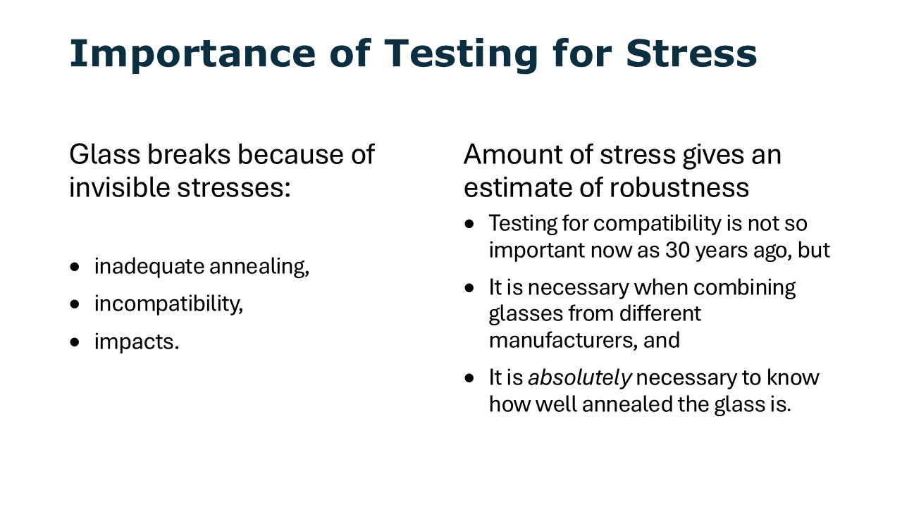
Testing for stress
A stress test is a means of determining how sound the fired piece is. It can also be used on smaller pieces to determine what stresses may be stored in the glass and to determine if the glasses are compatible.
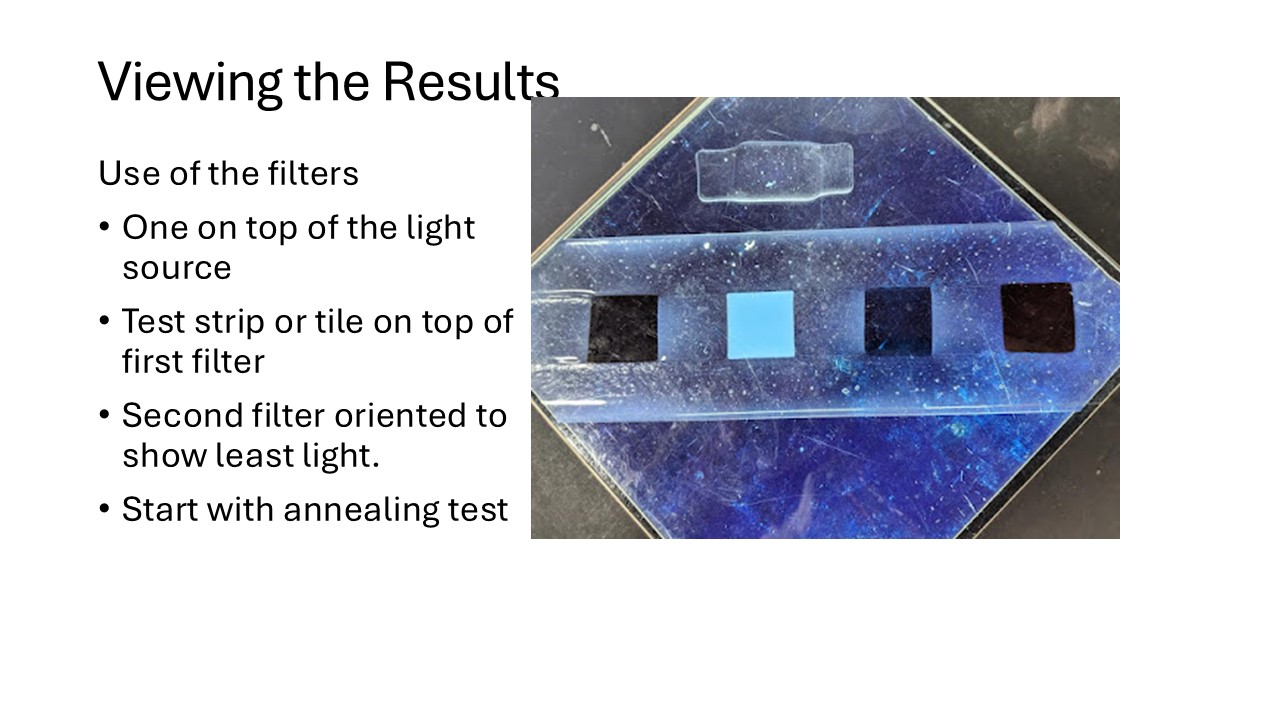
This tests for both stress and compatibility. These give notes on the use of the polarised filters.
Strain Point
The strain point is the temperature above which the viscosity of the glass is low enough that it is rarely subject to thermal shock, because it is no longer brittle. That temperature is determined by the glass’s viscosity, which is achieved at different temperatures for different glass, such as float glass.
Repair
I suggest placing a dam around the piece before firing for a repair. This can be thick fibre paper backed with kiln furniture, or some other circular material to confine the piece, in case the crack develops into a full break during the firing.
The Ramp Rate I suggested of 55°C/100°F per hour is because of the existing cracks. This is to avoid inducing additional stress to the piece during the temperature increase. Once the strain point is passed, the rate can be increased. I suggest the rest of the firing should be as for 12mm / 0.5". The anneal soak and cooling are given in the Bullseye document Annealing Thick Slabs, Celsius and Fahrenheit, which is applicable to "CoE 96" glasses, except for the anneal soak temperature.
Further investigation
I suggest two e-books which will be very helpful in your exploration of kilnforming:
Kilnforming Principles and Practices, by Stephen Richard
Firing Schedules for Kilnformed Glass, by Bob Leatherbarrow
Both are available from Bullseye or the authors.