Thick slabs often involve numerous firings of increasingly thick work. I am using an existing example, with their permission, of the first stages of a thick landscape. The initial concern was with bubbles in the first layup, then the strategy for firing the thick slab.
Plans
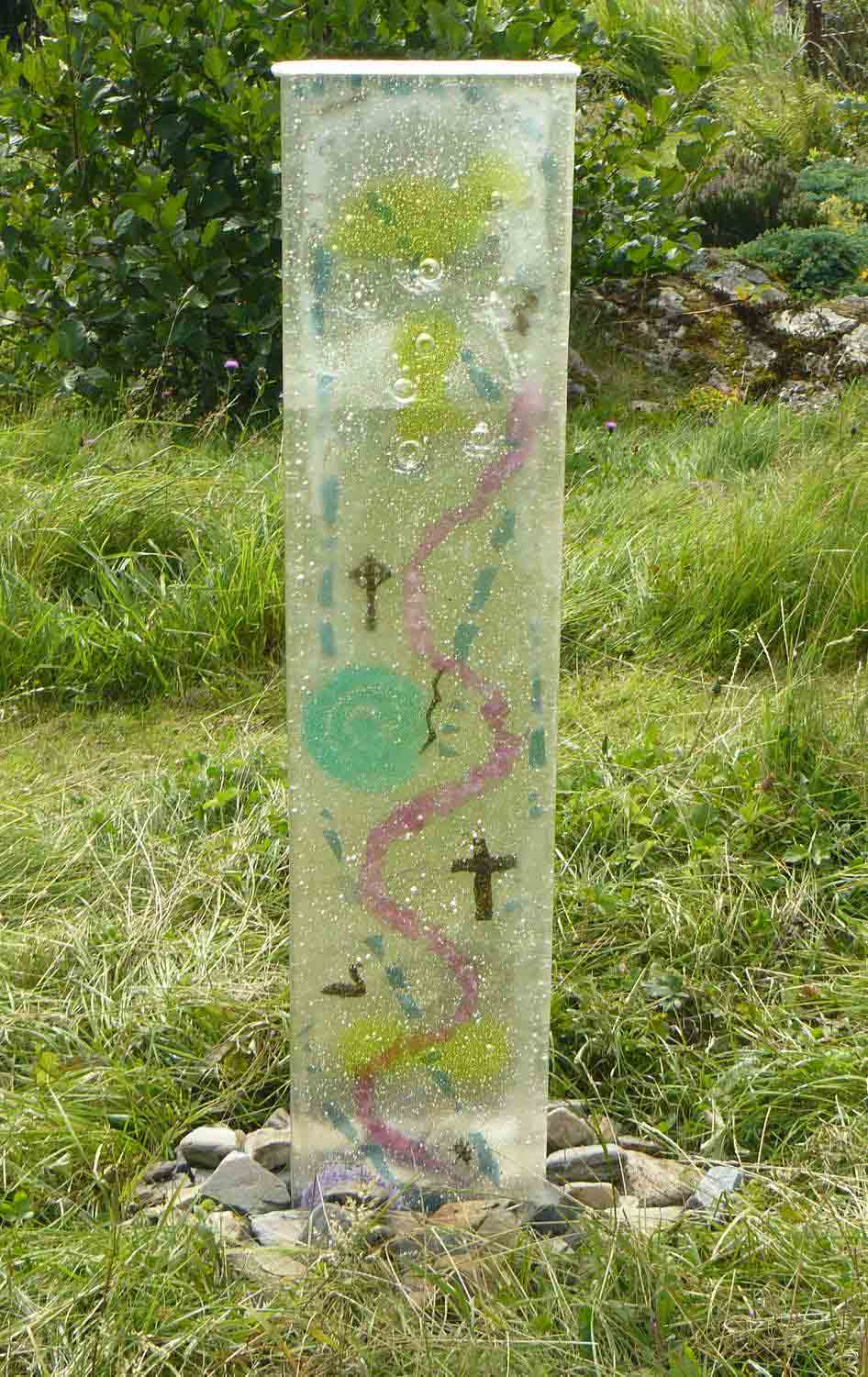
This is the first part of a landscape with depth. It will be fired 5-7 more times. This first piece will be inverted for the
next firing with the clear facing up, to avoid reactions between the colours. It is similar to an open face
casting. There is a Bullseye Tip Sheet on open face casting that will give a lot of information.
Layup
 |
| Picture credit: Osnat Menshes |
This work has a base of clear that is mostly overlaid with one layer of 3mm pieces, although in some places another layer, and there are some pre-fired elements as well. It is fired on Thinfire shelf paper.
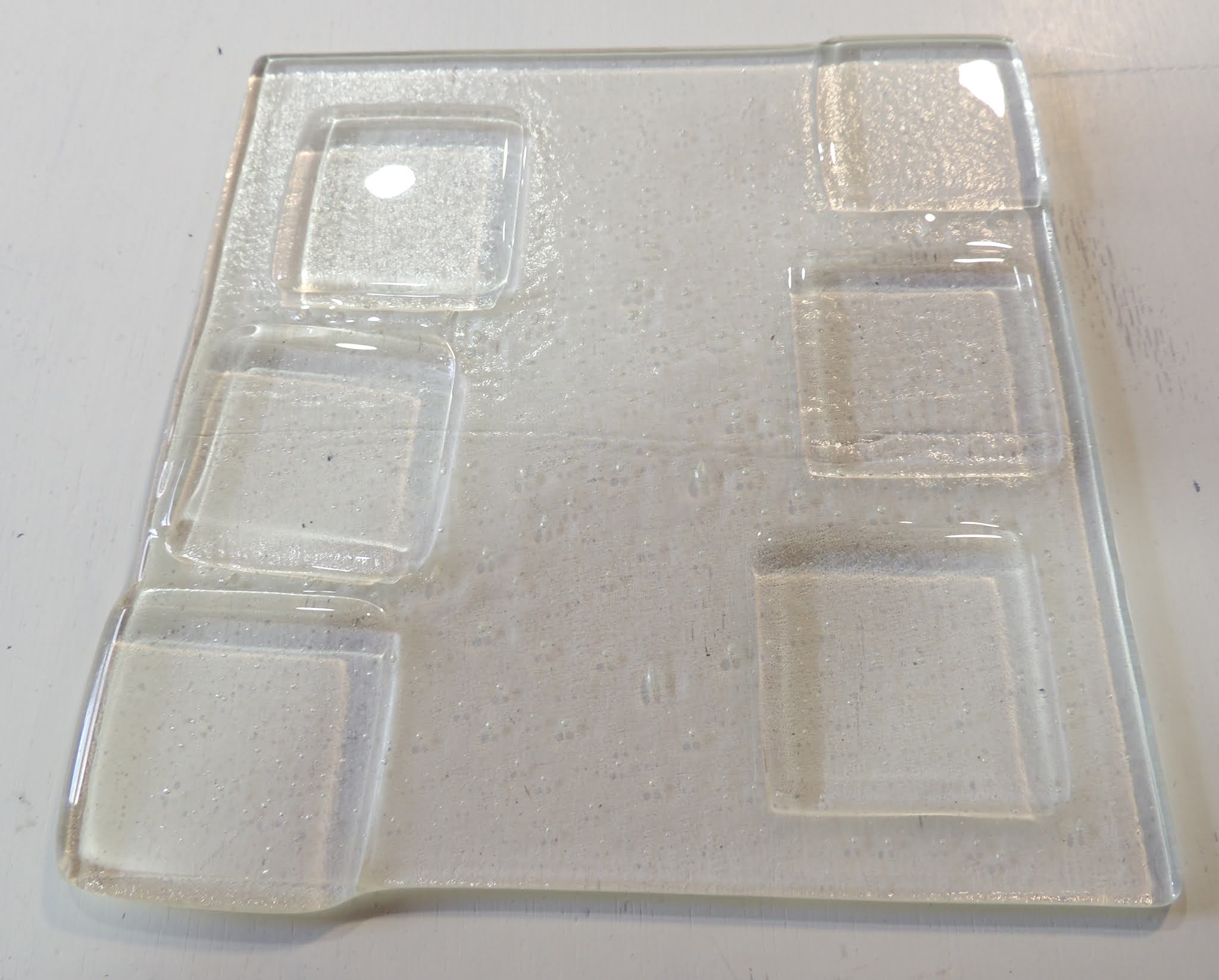
Bubbles
There is concern about the number and size of the bubbles after the firing, and how to avoid them. Will they grow over the multiple firings?
The many small bubbles are characteristic of kilnformed
glass. The few larger bubbles may result
from the frit that is under the pieces that form the top surface. And there are some overlaps of clear over
colour that may form pockets where air can collect. I advise leaving the scattering of the frit until all the decorative pieces are in place. The bubbles will migrate toward the top during
the multiple firings. They will not grow
in size unless they combine during the upward migration. A later suggestion about
reducing the number of firings will reduce the bubble migration and risk of
increasing in size.
 |
| Picture credit: Osnat Menshes |
Schedule
Proposed Schedule (Temperatures in degrees Celsius)
1: 180 – 560, 30’ I would go to 610 for 30'
2: 25 – 680, 120’ I would use only 30'
3: 220 – 810, 15’ I would set the top temperature at 816, 15’.
4: 9999 – 593, 30’ Eliminate this segment.
5: 9999 – 482, 120’ I suggest one hour soak
8: 55 – 370, off 83 – 427, 0’
7: 150 – 371, 0’
8: 330 – to room temperature, off.
Eliminate segment number 4. Any temperature equalisation done at this
temperature, is undone by the AFAP to the annealing. The temperature equalisation occurs at the
annealing temperature. No soak at an intermediate temperature is required. This blog post gives some information about annealing above and below the annealing point (Tg).
Firing Incremental Layers
The plan is for five to seven more firings. Continuing to build up the thickness on
each firing, may have some problems.
- There is increased risk of compatibility problems when firing a piece to full fuse many times.
- There is a risk of more bubbles and of the existing ones becoming larger as they move upwards and combine with other smaller ones.
- With each firing the thickness is increasing and so becoming a longer firing. This is because the heat up, annealing, and cooling each need to be longer. For example - 6mm needs 3hour cooling, 12mm needs 5 hours, 19mm needs 9 hours.
Multiple Slabs
These are the main reasons that I recommend firing a series
of 6mm slabs separately and combining them in one final firing. Firing a series of 6mm slabs and then combining
them in a single long and slow final firing has advantages.
- The individual pieces do not need to go through so many full fuse firings, reducing the risk of compatibility problems.
- The small bubbles in each firing will not have the chance to rise through all the layers to become larger.
- The total time in the kiln for the combined pieces will be less than adding layers to already fired layers.
Examples
It is often difficult to convince people that firing by
adding incrementally to an existing slab, longer firing times are required than
by firing a group of 6mm slabs and a single combined firing of all the slabs. I give an example to illustrate the
differences.
Annealing
Assume there are to be a total of eight firings (existing
6mm slab and 3mm for each of seven more firings). Also assume that each additional firing is of
3mm. This makes a total of 28mm. Compare
annealing and cooling times for each firing:
Firing
thickness anneal and cool (hours minimum)
1 6mm 3
2 9mm 4
3 12mm 5
4 15mm 7
5 18mm 9
6 21mm 11.5
7 25mm 14
8 28mm 17
Total 70.5
hours annealing time (minimum)
To fire up 5 six millimetre slabs takes less time – 3
hours annealing and cooling time for each firing cumulates to 15 hours. Add to that the final firing of 17 hours annealing
time. A total of 32 hours. This is half the time of adding to the
existing slab at each firing.
An additional advantage of firing 6mm slabs and combining them, is that bubbles can be squeezed out more easily in the final thick slab fring because of the combined weight of the slabs. You could make the individual slabs a little thicker, but that would involve damming each slab. Not an impossible task of course. And it would change the calculations, by reducing the number of firings.
Heat Up
Another time saving is to use the second cooling rate from the Bullseye document Annealing Thick Slabs as the first up ramp rate. Take this rate up to a minimum of 540˚C. Although, this is an arbitrary temperature above the strain point to ensure all the glass is above the brittle phase. It is possible to maintain this initial rate to the bubble squeeze. But with the slow rises in temperature required for thicker slabs, it is sensible to increase the rate from 540 to bubble squeeze to reduce the firing time. Once past the bubble squeeze a more rapid rate can be used to the top temperature.
The heat up times could be about half the minimum cooling times.
A worked example (with
certain assumptions) would be:
Firing
thickness time to top temperature total time.
1 6mm 6.3
2 9mm 7.1
3 12mm 8.4
4 15mm 10.7
5 18mm 15.9
6 21mm 19.4
7 25mm 25.1
8 28mm 29.1 ca.122 hours
But firing five times for 6mm equals 31.5 hours plus the final firing up of 29.1 hours equals a total of 60.6 hours. Again about one half the time of progressively building up a base slab to the final thickness.
Savings
This example shows
that approximately 90 hours of firing time can be saved by making a series of
six millimetre slabs and combining them in a final firing. There is the additional advantage of reducing
the occurrence of bubbles between the layers in the final firing because of the weight of the
combined slabs.