Sunday 29 March 2020

Choosing a Soldering Iron

The iron used to solder must be of a high enough wattage to readily melt the solder and be able to reheat fast enough to maintain the necessary melting temperature. The tip can't be so small it can't maintain the heat nor so big it covers more area than wanted.


For example a 75 or 80 watt iron is sufficient to begin soldering with, but it will continue to get hotter, as it has no temperature control. An iron of this type should be used with a rheostat in order to prevent overheating while it is idling.


Most temperature controlled irons seem to be produced in 100 watts or higher. These internally temperature controlled irons maintain a constant temperature. They are normally supplied with a 700F° bit (number 7) and is sufficient to melt the solder without long recovery times. You can obtain bits of different temperature ratings, commonly 800F° and 600F°. You can also several sizes of tips for different detail of work.

  For volume work you can obtain temperature controlled irons of 200 watts and more.


It is also possible to obtain a Japanese made soldering iron with the rheostat built into the handle.


Soldering irons

General
Historically soldering tips were copper, placed in braziers. One tip at a time was used; when the heat had transferred from the tip to the solder (and depleted the heat reserve) it was placed back in the brazier of charcoal and the next tip was used.

Much later gas irons were in common use. These used a gas jet to heat the soldering bolt/tip. They are very fast, but require significant amounts of experience to properly regulate the temperature.

Currently, electric soldering irons are used; they consist of coil or ceramic heating elements, which retain heat differently, and warm up the mass differently, with internal or external rheostats, and different power ratings - which change how long a bead can be run.

Selection
The soldering iron used must be of a high enough wattage to readily melt the solder and be able to reheat fast enough to maintain the necessary melting temperature. The tip can't be so small it can't maintain the heat and not so big it covers much more area than wanted.

For soldering leaded panels a 100w iron with a 3/8" temperature controlled tip that maintains a constant 370°C (700° F) is suitable.

For copper foil a higher temperature controlled tip is used. This normally runs at 425°C (800°F). Sometimes a tip of ¼” is used where more delicate beads are being run. But there is little difference in the resulting bead - only that the smaller bit takes slightly longer to heat up.

If a lot of soldering is required that has sustained heat requirements, you might consider a 200W iron. These can deliver heat more quickly and evenly than those with lesser wattage.

Trimming the Came on Site

There are a variety of reasons for the panel not fitting the opening easily. These can range from poor measurements through parallel, or trapezoidal openings to irregular perimeters of the openings.


In the cases of irregular openings, you can trim the edge cames if you have used 12mm (1/2”) or more wide came. The quickest way of trimming cames to fit the opening is to use a rasp or “surform” tool. The open nature of the teeth, allows the lead to fall away. It is much quicker than using a lead knife, and it puts less pressure on the panel.

Cementing Leaded Panels, part 3

Polishing Lead Cames

Use a soft brush to polish lead came. Don't pick out the cement until the polishing is done, as it provides the colour for darkening and polishing the lead and solder joints. The action with the polishing brush should be gentle and rapid, much like polishing shoes. If the shine does not come, you can use a very little stove blackening (carbon black mixed with a little oil) If you use a lot, you will have a big clean up job. A little stove blackening spreads a very long way.


realglasspainting.com


Before turning the panel a final time, put down paper or cloth, to avoid scratching the solder joints while polishing the other side. The result should be shiny a black came and solder joints that does not come off the way a final buffing with stove blackening does.


Finally, pick out any remaining cement.


Rest horizontally with weather side down for traditional installations. If the panel is going into a double or secondary glazed unit, you may want to reverse this. The reason for having the smallest exposed cement line on the outside is to allow the water to run off the window with the minimum of area to collect. In a sealed unit or for secondary glazing, you may want to have the smallest amount of cement showing inward for appearances, as there is no weathering reason for the traditional method.


Rest for a day. Pick out the cement again. If the cement was stiff enough, there should be no need to do any more picking at the cement after this.

Cementing Leaded Panels, part 2

Part 2: Setting Up the Cement

After the pushing the cement under the cames on both sides, flip the panel over and begin a firm rubbing to push addidional cement into the gaps between the lead and glass on this side. Sprinkle the used dust from the bench top over the panel and rub in all directions. This begins to set up the cement by helping to provide a stiff skin over the more fluid cement. Brush until the whiting is largely off the panel. Turn the panel and do the same for the other side. Several applications of whiting/sawdust are required to give a sufficiently thick skin to reduce the amount of spreading, leaking or weeping cement.


Once both sides have been done a couple of times, begin to concentrate the brush strokes along the lead lines rather than across. This will begin the cleaning phase and also begin to darken the came. Repeat this on the other side.


After a few turnings, most of the cement will be cleaned from around the leads. Don’t try to get all of it away, you will need that colour for polishing. The glass will be shining, and any felt tip marks you made on the glass will have gone too. Clean up the dust from the panel and bench in preparation for polishing.


Part 3

Cementing Leaded Panels, part 1

Part 1: The Start

Cementing panels is as old as leaded glass - about 1,000 years - so it is a time-proven process using simple materials. The object of cementing is to make a leaded panel weather/water tight and sturdy. It can be messy and dusty, so putting on an apron and a dust mask are a good idea.


Start on the side that is already facing up after soldering. This normally will be the rough side. This way you do not have to move the panel much until it has stiffened with the addition of the cement.


Cover all open bubbles, rough glass (waffle, ice, etc.) and all painted glass with masking tape. Put the tape over all the relevant areas of the panel, then use a sharp knife (X-acto, scalpel) to cut the tape at the edges of the came. The cement will go under the came, but not into the texture of the glass. This will make the clean up of the glass much easier after cementing.


You can purchase commercially made lead light cement or you can make your own.

With the panel on the bench, put a dollop of cement on the glass and rub it in all directions with a stiff, but not hard, bristle brush to force it under the lead. 


Bovardstudio.com

When the cement has been pushed under all the cames, but with a slope of cement showing, spread a little fresh whiting or sawdust on the panel and gently push it against the cement under the leads. This begins the setting process and keeps the spreading cement from sticking hard to the glass or bench.


bovardstudios.com


Turn the panel over to cement the second side the same way as the first. If the panel is a large one, you may want to use a board to support it in these early turning stages. No gaps can be tolerated in the cementing. Cement leaking out the other side is good evidence that all the gaps between the glass and the came are filled. Again, after cementing, sprinkle new whiting/sawdust over the second cemented side and rub it gently into the exposed cement.


Part 2
Part 3

Friday 27 March 2020

Reinforcement

Reinforcement is probably the most important design element in stained glass. Without adequate reinforcement, all other effort and results are secondary, because an inadequately reinforced work will not survive, and that is sad.

GuidelinesThere are no all-encompassing reinforcement rules. There are however some basic guidelines:
  • Restrict non-reinforced panels to between 2 and 4 perimeter metres (a rectangle of 1 by .5 meters up to a square of 1 meter).
  • An abundance of horizontal or vertical lead lines within the leading concept are most likely best served by a vertical reinforcement system.
  • A diagonal or bent reinforcement bar dilutes its reinforcement capacity in proportion as it deviates from the straight. Such supports serve to merely stiffen the section.
  • Know that most reinforcement systems provide only lateral reinforcement.
  • In most architectural situations which adhere to sections of 4 perimeter metres, reinforcement will usually be 12” to 18" apart in vertical accommodations, with an average around 15".
  • Placement of reinforcement should be established on the initial scale layout in which the design is to be done. It should not be an addition after the whole is designed. That increases the likelihood that the reinforcement will be an intrusion upon the design.
  • Very tall or wide windows should have an armature of some sort. This is commonly "T" bars for the panels to rest upon without transferring their weight to the panel below. Other more complicated armatures can be seen in large windows, such as at Canterbury Cathedral.

With diamond and other quarry lights, reinforcement placement cannot always be equally spaced. In such instances, it is probably best to have the shortest distances between the reinforcement at the base of the section where the weight creates the greatest likelihood of buckling.

Inserting Glass into the Came

If you have consistent difficulty in sliding the glass into the came, you should consider dressing the came before use. Dressing the came consists of running a fid or other hard material along each of the four flanges of the came. In doing this, you are pressing each flange in turn down against the bench or other smooth surface.


Dressing the cames gives a slight bevel or ramp for the glass to slide over the edge of the came and into the channel of the came. You can dress the whole length at once, or as you cut the pieces off from the main length. Dressing shorter pieces is less likely to bend the came.


Of course there is a second stage of dressing the lead came upon completion of the soldering.

Structural Reinforcement


Leaded light panels often require additional support against wind pressure or vibration. Whether this is needed depends on the size and location, e.g. if in a door or a ventilating window that is constantly being opened and shut.  Large leaded glass windows need some bracing against the force of wind and rain. This can be achieved by using one of the following supports:
  • Saddle Bar
  • Reinforcing Bar (Rebar)
  • Steel Core or Steels
  • Zinc Section

Saddle Bars are the strongest method of support and are used in large external windows for preventing panels from bowing inwards. They resist wind pressure in exposed situations. Saddle bars form part of the latteral support structure of the window. These bars are attached to the panel with copper or lead ties.  These ties are soldered to solder joints across the narrow width of the panels.  The bars are fixed to the perimeter of the opening either by the mouldings or by being inserted into holes in the frame. The sides of the opening provide the ancor points for the bar.  The panel is fixed to the bar by twisting the ties around it.


A saddle bar fixed in position at the side and the ties being twisted around the bar.


Sometimes the opening is divided by sideways "T" bars.  Generally the leg of the "T" faces outwards and the panel is set onto the ledge formed by the leg of the "T".  This leg often has a series of holes drilled in the leg, for pins to be inserted to hold the panel in place until the sealant has cured.


An example of "T" bars being used on a small side opening window


Rebar is another external support.  It generally is a zinc coated steel strap about 2mm by 10mm and asl long as needed to cross the panel.  This tends to be soldered directly to the panel at the solder joints either on the inside or outside. One advantage of this material is that it can be bent to conform to the lead lines of the panel.  In consequence it is not as stiff as saddle bars are.


Steel core
Steel cores take two forms - either steel-cored lead or steel strips fitted into the lead cames when leading.  The steel cored lead came is less available nowadays.  They are mainly used in domestic glazing where support is required particularly in leaded lights with diamond panes when they are inserted in continuous diagonal leads. The steel cores are not adaptable to significant curves.


Steel cored lead came cut away to show the steel core


Zinc

Zinc section came is often used to frame a panel that is not glazed into a window or frame. It has been used in the past for both straight and curved lines.  Using it for curves requires a came bending machine to give good, regular curves.  It gives a panel strength for ease of handling, but does not resist sagging or bowing at the centre.  The other disadvantage of zinc is that it corrodes much faster than lead.


Image showing a variety of zinc came

Wednesday 25 March 2020

Scheduling to Room Temperature


Why Schedule the kiln to room temperature? The kiln will cool slowly enough at the final stages.


How do you know?

Relatively large thick pieces need slow rates of cooling below 370°C.  Complex tack fused pieces require slow cooling rates as well as the long annealing soaks. These required rates of cooling may be slower than your kiln’s unpowered rate of cooling.

This means you need to know the natural cooling rate of your kiln from 370°C down to room temperature to be sure you are cooling at a suitable rate. The method described in this blog post gives you information on how to calculate the natural cooling rate of your kiln.

I program my firings to about twice room temperature. Yes, the kiln does not turn on much during that time,  but when I crack my kiln open to speed the cooling, the switching on of the relay tells me I am cooling faster than programmed, and I can reduce the size of the opening to avoid too rapid cooling of the piece.

The following chart is a way to assist in recording your kiln’s unassisted cooling temperatures against time to give you the natural cooling rate at various temperatures.


Natural Cooling Rate of the Kiln

Kiln Name: Cooling Rate
observ'n Time (hr:min) Temperature Difference rate/min  rate/hr 
1         : Time (mins) Temp. =temp/mins .=temp/min*60
2         :
3         :
4         :
5         :
6         :
7         :
8         :
9         :
10         :
11         :
12         :
13         :
14         :
15         :
16         :
17         :
18         :
19         :
20         :

Wednesday 18 March 2020

Candle shades


These kinds of drapes are generically known as handkerchief drops, as they form the kind of shape that is formed by holding the cloth in the middle and letting it drape.  They can be done as small drapes over kiln posts, cocktail shakers, and much larger forms.


Two heights of new cocktail shakers


A well used cocktail shaker with kiln wash


A kiln post wrapped in preparation for firing


Two short kiln posts after firing


When preparing several drapes to be fired at one time you need to consider several factors.


Higher in the kiln is hotter.
The heat in a kiln, as in an oven, is greater the higher in the kiln is supported.  This means that taller supports will drape quicker than shorter ones. The consequence is that all the drapes should be of the same height.

A single layer that has begun to stretch at the shoulder of the former 


Larger spans fall quicker than smaller.
The more of the glass that is unsupported, the quicker it will fall, even at the same height. This is because the larger amount of unsupported glass has more mass than a smaller one and so falls quicker.  Plan for all the glass to be of similar sizes.

These two were fired at the same time. The back one is larger than the front 


Different shapes fall in different ways.
Squares and circles are the most common shapes used in a  drape. The corners of squares are points that are further away from the centre of the support than the sides.  These points begin to fall first, drawing the sides in later in the firing.  Circles form a taco shape before the ends of the “taco” begin to fall.  This deformation of the circular “taco” takes longer than a square takes.

Care needs to be taken that the glass does not thin excessively at the shoulder of the support.  There is less difficulty, if the same shapes are fired together as different heat work is required for each shape.


Observation by peeking is required to stop free drops at the right time.
As in all drapes, it is important to observe the progress of the drape at intervals.  This is best done by quick peeks to note the development of the shape and to move to the cooling segment when the drape is complete. This also requires a scheduling of a long soak and knowledge of how to advance the kiln controller to the next segment of the schedule.

Wednesday 11 March 2020

Kiln Maintenance


Switch off the kiln before doing any maintenance.

Before or after each use

Vacuum the inside of the kiln. Use a low suction setting, especially on fibre walls and ceilings. Stronger suction is possible when cleaning a brick floor.

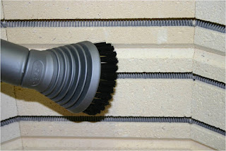
Example of vacuuming around elements
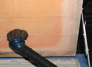
Example of vacuuming lid without elements

An alternative to vacuuming the elements is to use the air compressor hose at low power to gently blow out any dust settled in the element grooves.  Do not do this for fibre insulated kilns, only brick.

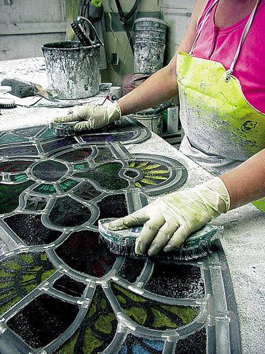
Check on the kiln furniture – including shelves, boards, supports. Are they kiln washed and without scrapes, scratches, gaps? Has the kiln wash been fired to full fuse temperature? In both cases, clean the used kiln wash off the shelf and renew.

Check that the shelves and other kiln furniture are without cracks.

Clean kiln furniture of dust and debris.

Check the level of any item newly placed in the kiln - e.g., mould, or shelf replacement - with a spirit level.

Two examples of two-way spirit levels

 Check on the conditions and placement of the thermocouple.

Check on the elements.  Some may be sagging or hanging out of their channels.  Use tweezers to bring the coils closer together.  This shortens the length of the element and it then can be pushed back into the channel.  It may not have to be done after each firing, but checking will catch things before sagging becomes a major problem.

When the shelf paper is exhausted lift out the thicker papers and vacuum the shelf.  The Thinfire and Papyrus papers can be vacuumed directly or gently swept up and placed in a container for disposal.  Do not introduce any moisture to help reduce the dust.  This is not good for the kiln or you, as it could induce shorting out of the elements.


Monthly

Electrical parts: check the elements and their connections (normally at back or side).

First unplug or switch off the power to the kiln.

Check the screws on the connectors for the element tails are tight. Loose connections cause the wire to vibrate at the connection during the power phase. They heat up enough to melt the wire at the connection. For a single element kiln, it will simply lose power.  In multiple element kilns the remaining elements work much harder to achieve the temperature and provide uneven heating.


If the connectors are badly corroded , they need to be replaced.  This can be done without replacing the elements. Unscrew the connectors and put new ones on.  If the connector is fused to the element wire, you need to cut the wire as close to the connector as possible to maintain a length of wire for the new connector to be fixed.


Check the condition of leads and plugs supplying power to the kiln.  Make sure they are sound, not frayed and not kinked. Replace any frayed parts.  Take out any kinks in the power supply cable.

Any support pins or wires should be firmly seated in the brick work or supported by sound hangers.


Check the level of the kiln floor and internal shelves on a regular basis and every time the kiln and its internal furniture is moved.


Making a schedule of maintenance checks and noting on it the dates checked is a good idea for those who need reminders.