Thursday, 2 January 2020

Flux

Flux is a material that provides a “wetting” action between the metal (lead, copper,and zinc, among others) and the solder.

There are various types of flux. Some are of more use in some circumstances than others. Among them are:


Tallow
This normally comes in a candle-like stick. It is made from rendered animal fat. Although this may put some vegetarians off, it is one of the best fluxes for leaded glass work and will work for copper foil, but is not generally preferred.  It is relatively natural, does not contain chemicals, and does not require re-application if left for a while. Over generous application does not produce any problems during the soldering. It just leaves more solidified tallow to clean after soldering. The cleaning normally requires a mild abrasive such as a brass or fibreglass brush to get the cooled tallow off the piece.


Oleic acid and other safety fluxes

Many of the safety fluxes are made of oleic acid (sometimes called stearin oil). These fluxes do not produce chemical fumes in the soldering process. They are easy to clean up with detergents and warm water. Safety fluxes require re-application if left to dry, as they are only effective while wet. Putting too much on leads to boiling off the liquid, making holes in the solder joint or line.


An example only.  There are many water soluble paste fluxes available


Chemical Paste fluxes

These fluxes come in a variety of compositions. You need to be careful about choosing, as some are very difficult to clean off the glass, solder line, or joint. They do produce chemical fumes, so a fume mask is advisable while using this kind of flux. The paste does not require re-application if left, so the whole piece can be fluxed at once.


Acid fluxes

Acid fluxes such as is in the core of plumbers solder are intended to clean the joint at the same time as acting as the wetting agent. These are not recommended for stained glass work as they can affect the glass surfaces, especially iridised glass. They do produce fumes that require the user to take precautions while soldering. The ease of cleaning relates to the particular composition of the flux, so testing samples is required before application.

See also:
Flux, an introduction
Fluxes, a description
The Purpose of flux
The action of fluxes
Soldering fluxes


Revised 1.1.25


Flux, an Introduction

Flux is a key contributor to most soldering applications. It is a compound that is used to lift tarnish films from a metals surface, keep the surface clean during the soldering process, and aid in the wetting and spreading action of the solder. There are many different types and brands of flux available on the market; check with the manufacturer or reseller of your flux to ensure that it is appropriate for your application, taking into consideration both the solder being used and the two metals involved in the process. Although there are many types of flux available, each will include two basic parts, chemicals and solvents.

an example of paste flux


The chemical part includes the active portion, while the solvent is the carrying agent. The flux does not become a part of the soldered joint, but retains the captured oxides and lies inert on the joints finished surface until properly removed. It is usually the solvent that determines the cleaning method required to remove the remaining residue after the soldering is completed. 


It should be noted that while flux is used to remove the tarnish film from a metal's surface, it will not (and should not be expected to) remove paint, grease, varnish, dirt or other types of inert matter. A thorough cleaning of the metal's surface is necessary to remove these types of contaminates. This will greatly improve the fluxing efficiency and also aid in the soldering methods and techniques being used.


Courtesy of American Beauty Tools


See also:
Flux, an introduction
Fluxes, a description
The Purpose of flux
The action of fluxes
Soldering fluxes

Snugging the Came to the Glass

It is important to have the came fit snugly to the glass (assuming the glass to be the right size and shape). If it does not, the panel is likely to grow beyond the intended dimensions.


To ensure the came is tucked snugly against the glass, you use a fid of firm material (wood or plastic, for example) to press against the heart of the lead. You can press directly toward the glass, or make multiple passes along the length of the came to ensure the heart is touching the glass all along its length.

You should avoid steel tools, because you may cut the lead, and if the blade is long you will not find it easy to fit along all of the curves.

Fitting the Glass to the Cartoon

Often you find that the next piece of glass does not fit properly. Possibly it rocks a bit in the came’s channel. Possibly it is simply just a little too big.  Wait! Don't adjust the piece just yet. It may not be the problem.

The first thing to do is to take the too-large piece of glass out and remove the came it fits into, to ensure the previous piece of glass is not too large. The glass should not overlap the cut line. If you have drawn your cut lines to 1.2mm (1/16”) you should see only the faintest line of paper between the glass and the dark cut line. 


If the glass seems too large, check that it is firmly in the channel of the previous came, as sometimes the glass catches on the edge of the came and does not go into the channel.


If that piece seems too large, the next check is to determine whether the apparently too large piece of glass really fits the cartoon cut lines. Place the glass inside the cut lines. You should see a faint line of paper between the glass and the cut line.


When you are sure both pieces of glass are the correct size, put the came back between them and check again. If the glass is still too large, check the length of the came. Make sure the came butting onto the came separating the glass is not too long. This is a common reason for lead panels to grow beyond their initial dimensions.


If the glass is the correct size and the butting cames are correct, replace the came. Put the too large piece of glass into the came and position it so it has the best fit to the next cut line. 


Do not be tempted to start reducing the glass at the visible portion.  After all, you cut it to the right size. It may be that the fit under the came is not very good.

To check use a felt tipped pen (Sharpie) to run along the edge of the came, marking the too-large piece of glass. Take it out and check on where the line is farthest from the edge of the glass. That is where you need to reduce the piece.


The nail points to the area that needs adjustment

When you have reduced the "high" spots on the glass so it fits under the came evenly along its length, you can begin to adjust the outer edge, if necessary.

A fuller description is here.


Leading Tight Curves

Sometimes it can be difficult to get the lead came to conform to the curves of the glass, especially on compound curves.  There is a method to make the leading more accurate.

When leading tight inside curves, bend the came into a tighter curve than is needed for the glass. Then roll it into the glass. Finally, run your fid or stopping knife along the heart of the came to ensure it is firmly against the glass. All this helps the came to fit snugly into the curve.


Revised 1.1.25

Tuesday, 31 December 2019

Gravity


One of the fundamental elements in kiln forming is gravity. When glass is hot it moves according to the effects of gravity and that has a big effect on all your firings.

The effects mainly cause:
  • Uneven thickness on shelves that are not level.
  • Uneven slumps into moulds which are not level or the glass is not levelled.
  • Uneven forming due to varying viscosities. Gravity acts on the softest parts of the glass first.
  • Faster or slower forming due to span width. With greater span, gravity pulls the glass into the mould more quickly than with a small span.
  • Gravity acts on things of greater thickness more quickly than those of lighter weight, given equal temperatures throughout. 
  • Surface tension (affected by viscosity and heat) is affected by gravity also. The glass will attempt to draw up or spread out to about 7 mm if there is enough heat, time, and low viscosity at full fuse temperatures.  At higher temperatures it will spread further as the lower viscosity allows.
  • The effect of gravity causes upper pieces to thin lower ones, as it presses down while the glass is plastic. This has the effect of making the colour of the lower piece less strong.

More information on each of these effects can be found throughout this blog and in the eBook Low Temperature Kilnforming available from Bullseye and Etsy.

Revised 1.1.25

Wednesday, 25 December 2019

Cutting Opalescent Glass


People often find cutting opalescent glass more difficult than transparent. My observation is that many people exert too much pressure in scoring opalescent glass by listening for the creaking/scratching sound. 

Not all glass is made the same, even by the same manufacturer.  Scoring different glasses sounds different with the same pressure applied.  But no more pressure should be applied to opalescent glass than to transparent.  Only about two to three kilograms (5 to 7 pounds) of pressure is required to score opalescent glass sufficiently to create the weakness that we exploit when running the score.

If you concentrate on keeping the pressure on both types of glass the same, you will hear different things.  On transparent glass you normally hear a creaking or light scratching sound and you do not get a whiteness along the score line.  If you hear same sound on opalescent glass, and a white appearance showes that too much pressure is being applied. 

The same pressure (2-3 kilograms) on opalescent glass gives only a rumble of sound - no creaking or scratching is heard.  You can test this 
  • Place a piece of glass on kitchen scales. 
  • Zero the scales with the transparent glass on it and 
  • Score without touching the glass with your other hand. 
  • Note the pressure you used.  
  • Zero the scales with a piece of opalescent glass on it. 
  • Score to the same pressure as on the transparent glass by looking at the readout on the scales.
Just as excessive pressure on transparent glass leads to erratic breaking of the glass, so it does on opalescent glass.  You may need some practice to stop listening for a sound and begin to feel the pressure you are applying to the glass. Once you do apply the same pressure to opalescent as to transparent glass, your success in scoring and breaking opalescent glass will increase.

Scoring and breaking opalescent glass successfully is the same for both transparent and opalescent glass.  Use moderate pressure and don’t listen for the sound.

Feel the pressure. Ignore the sound.


Revised1.1.25

Wednesday, 18 December 2019

Annealing Range for Unknown Glass

It is possible to anneal unknown glass with some degree of certainty by using what is known as the slump point test.  This will not be as accurate as a factory determined test, so you do have to extend the range over which you do the annealing.  

The annealing of glass with unknown characteristics is possible in two ways - shotgun and calculated.  The examples here are for 6mm thick glass.  The soak and cooling times need to be extended for thicker glass.  


Both the shotgun and calculated approaches exemplified here assume glass of 6mm thickness.  For thicker glass the soak time needs to be extended and the anneal cool rate slowed more than indicated above.  Using the Bullseye chart for annealing thick slabs will give you an indication of the relationship of thickness to speed.


1)  One is the traditional shotgun approach – pick an arbitrary, but slightly high temperature, and soak for a minimal amount of time there. Then go very slowly through the next 55°C.  This may be as slow as 25°C per hour, followed by a doubling of that rate for the next 55°C. Then double again to 300°C or less.

2)  By using the slump point test and the calculations, you will be sure of the annealing point/temperature equalisation point within 10°C.  The approach here would be to soak for half an hour at the calculated temperature, followed by a slow drop of 50°C per hour to 55°C below annealing soak and then at 100°C/hr to 110°C below your chosen temperature equalisation point. The final cooling could be at 200°C to room temperature.

2a) An additional tweak to the slump point test calculations is to use the Bullseye concept behind their recommendations for thick slabs.  Using their concept, you reduce the calculated annealing point by 30°C from the calculated annealing point to do the temperature equalisation soak at the lower end of the annealing range.  Having calculated the annealing point, you reduce that temperature by 30°C and soak for  a longer time of 60 minutes and at a slower rate as noted in the chart.

In using the chart for unknown glass you substitute the calculated temperatures, but continue to use the rates and times indicated.  An example:

  • You have calculated that the annealing point is approximately 535°C.
  • Subtract 30°C from that to get a equalisation temperature of 505°C.
  • Assume the piece is uniformly 12mm thick or 6mm tack fused (when you want to use rates for  twice the actual thickness to account for the difficulties in tack fusing). 
  • For a 12mm thick piece your soak time at 505°C will be two hours.
  • The cooling rate for the first 55°C is given as 55°C per hour according to the chart. Therefore the first cooling segment will be 55°C from 505°C to 450°C.  The second will be 99°C per hour from 450°C to 395°C.  The third rate will be 330°C per hour from 395°C to room temperature.


You can see that the times and rates are taken as given by the chart (as determined by the thickness of your piece), but the temperature set points are determined by the calculations for the glass you have tested.

When determining what temperature you should use to anneal a glass about which you are uncertain of its characteristics, you can use one of two basic approaches.  Pick an arbitrary temperature and soak for some time there and then proceed slowly in 55°C segments to about 370°C.  A second more certain method is to use the slump point test to determine the annealing point and then apply the Bullseye chart for thick slabs for the soak times and cooling rates.

Further information is available in the ebook Low Temperature Kiln Forming.

Wednesday, 11 December 2019

Use of Sal Ammoniac block


A block of sal ammoniac is an excellent aid to keeping your soldering iron tip (or bit) clean and able to hold a small blob of solder.

A description of what sal ammoniac is and the safety precautions in its use are here

  • Place the block in such a way that it cannot slide around as you rub your iron over it.
  • Place your hot soldering iron tip on the block until it begins to smoke. 
  • Move your iron slowly back and forth along the block.  Initially, the block will be black from the contaminants coming from the soldering iron bit.  As you rub the bit along the block, it will begin to clear. As it does, you can add a touch of solder and turn the bit over to check whether there are still any black spots on the face of the bit. 
  • If these spots are persistent, you can use a brass wire brush to help clean the contaminants off.  
  • Add a touch of solder and return to rubbing along the block.  
  • Repeat this check until the whole bit is bright and holding a small blob of solder.  
  • This completes the tinning process on one side.
  • Repeat this process for the other side too.
  • Leave a small blob of solder on each side of the bit to protect the bit from oxidising.  
This cleaning process should be done at the end of each soldering session if the bit is not clean.   The frequent quick wipe of the bit on a damp sponge or a ball of brass swarf cleans the bit as you work.  The sal ammoniac block is for cleaning persistent contaminants off the bit.

Wednesday, 4 December 2019

Pot Melt Temperature Effects

Image credit: Craft Gossip

When firing a pot melt, you have to consider how high a temperature is needed.

Viscosity reduces with higher temperatures which increases the flow and reduces the length of soak, although there are often some undesirable opacifying effects at prolonged higher temperatures.

The size of the hole is also relevant to the temperature chosen. The smaller the hole, the higher the temperature will have to be to empty the pot in the same amount of time. Of course, you can just soak for longer at a lower temperature to achieve the desired object of emptying of the pot without changing the temperature.

Using the same principle, the larger the hole the lower the temperature required to empty the pot in a given amount of time.  So, in general the larger the hole in the pot, the faster it will empty, given the same temperature.

The temperature used to empty the pot will need to be between 840C and 925C (1546F and 1700F).  The problem with temperatures in the 900C to 925C range is that the hot colours tend to change, e.g., red opal tends to turn dark and sometimes become brown. Some transparent hot colour glasses also opacify. There is also the possibility that some of these glasses will change their compatibility with others in the range.

The best results seem to come from temperatures in the 840 to 850C range with longer soaks than would be required at 925C.  Also remember to give melts a longer than usual anneal as they will be thicker than 6mm at the centre - sometimes as  twice the edge thickness, which will require annealing for twice the thickest area.

Revised 2.1.25

Soldering old lead


This is normally only a requirement when repairing old windows. Usually either to join new lead to the old, or to repair breaks at the original solder joint.


You will need to clean the lead down to the bright metal at the joints. This is more than a rub with steel wool. You need a glazing nail to scratch through the oxidisation layer, the corner of your lead knife, or in cases of mild oxidisation, a brass wire brush might do. But not a steel one as that may scratch the glass and any painting.  

Do not clean the oxidisation off the lead elsewhere. That is a protective layer already formed which leads to the longevity of the came. It is best to leave oxidised lead alone rather than expose the metal to further oxidisation.

Getting to the bright metal where you want to solder the joint means the flux can act appropriately and help the solder form a secure joint.  Otherwise only a weak, cold joint is possible.

Note that you always need to use dust masks or other breathing protection.  You need to have the work area well ventilated and need to do a damp wipe down of surfaces to reduce the amount of lead oxide in the work space.

Wednesday, 27 November 2019

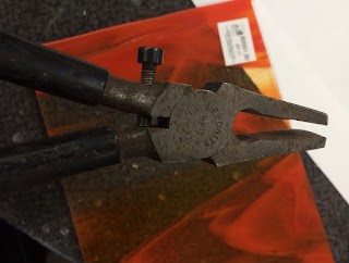
Using Cut Running Pliers Without Cushions


Using Cut Running Pliers Without Cushions

There are a wide variety of cut running pliers for different purposes.  A description of some of them is here.


This post is to describe maintenance and use of this kind of cut runner.


The plastic covers that come with these cut runners eventually wear out.  The replacements are hard to find. There are things you can do other than buying a new pair just for the shields.

You can dip the jaws in tool coating compounds such as Plastidip.  This does not last as long as the plastic, but is easy to re-do.

You can wrap the jaws in tape.  Electrical tape, duct tape or even self-adhesive elastic bandage will do the job. Again, not long lasting, but easy to replace.

Or

You can use the cut running pliers without any covering on the jaws.  “You can’t do that. You will crush the glass!” is the response I hear.  You can use them bare. I do, and so can you.


The key is in the adjusting screw.  It is there not just to tell you which is the top of the pliers; it has a function too.  That screw adjusts the opening of the jaws to the thickness of the glass. 


A simple way to ensure you have the correct opening is to put one corner of the jaw on the edge of the glass with the jaw opening less than the glass is thick. Then tighten the screw until you feel the handles of the pliers begin to open.  Then you have the right opening for the thickness of the glass. 


It ensures you cannot crush the glass, as the jaws will not close at the centre to be less than the glass thickness. 

You also have a more direct feel of the glass without the spongy connection of the plastic. You can sense the glass beginning to bend just before the score runs due to the gentle pressure of the jaws of the cut runners on either side of the score.

Whether you use the cut runners with or without cushions on the jaws, it is important to keep the adjustment screw lubricated so you can adjust the width of the jaw opening for different thicknesses of glass.


Wednesday, 20 November 2019

Pot Melt Schedule

I usually use a schedule like this for pot melts:

  • 100C/hr to 220C (180F/hr to 438F) for 20 minutes ; approximately the crystobalite inversion temperature – to be kind to the pot.
  • 220C/hr to 570C (396F/hr to 1090F) for 20 minutes; approximately the quartz inversion temperature – again to be kind to the pot.
  • 220C/hr to 677 (396F/hr to 1250F) for 30 minutes; the bubble squeeze temperature to allow larger bubbles to escape from the pot before melting begins.
  • 330C/hr to 850C (595F/hr to 1564F) for 120 minutes;  to ensure there is plenty of time to empty pot. 
  • AFAP to 805C (AFAP to1482F) for 30 minutes; to allow thickness equalization and also to allow bubbles to pop and seal.
  • AFAP to 482C for 120 minutes; this temperature is for Bullseye, but substitute the annealing temperature for your glass.
  • 55C/hr to 427C (100F/hr to 800F), no soak (for 6 to 12mm thickness)
  • 99C/hr to 370C (180F/hr to 700F), no soak.
  • 200C/hr to 150C (360F/hr to300), end.
  • Allow to cool to room temperature in the kiln

Revised 5.1.25

Pot Melt Contamination

Pot melting occurs at temperatures above that for which kiln washes are designed. This means the kiln wash most often sticks to the back of the melt.

If you put only fiber paper – Thinfire, Papyros, or standard 1mm or 2mm fibre paper – at the bottom, the dripping glass will tear and move it about.  It also tends to incorporate fibers from the refractory papers into the melt.  It is best to avoid fibre papers of any kind on the base.  Using fibre paper around the edges of dams, if you use them, is better than simple kiln washing of the dams.

From wikihow


If you have a sandblaster, it is easy to take the kiln wash off leaving a matt surface. You can live with this for many purposes, but if you want a more polished surface you can take the melt up to fire polishing temperature to shine up the surface. You will need to flip this over and fire again, if the original top surface is what you want to present.  Or if you like the new shiny surface, use it as is.

If you are going to cut the pot melt up for other uses, there is no need to fire polish as the surface does not matter, only the cleanliness, and removal of contaminants.


There is another thing you can do to avoid kiln wash contamination.


The best solution appears to be to put a disk or rectangle of glass on top of fibre paper. It can be clear or any colour you wish, but needs to fill the area enclosed by the dams. This seems to keep the fiber paper from tearing and being incorporated into the glass, even though the base will have the fibre paper marks.


It also works very well when you are confining the melt to get a thicker disk. Make sure you have kiln washed the sides of the container or dam very well, in addition to 3mm fibre paper arranged so that it is 3mm narrower than the expected final thickness, or any excess glass may stick to the dams. The means of arranging the fibre paper around the dams is given here. You may need to grind the marks off the edge of the disk, but this is much easier than grinding it off the bottom.

Wednesday, 13 November 2019

Separators sticking to Opalescent glass


It is worth thinking about how fast you fire pieces, especially where your current working temperature and rates of advance are giving difficulties.  One common difficulty is where opalescent glass picks up kiln wash or fibre paper and partially incorporates it, requiring a lot of work to remove it. 


At higher temperatures opalescent glass seems to incorporate some of the separator, especially near the edges.  It does not seem to matter whether kiln wash or fibre papers are used – there is frequently a little pick up.

The difficulty is achieving the profile you want without the higher temperatures.  This is where heat work concepts can assist.  Glass reacts to the heat applied, rather than simply the temperature.  Heat is a combination of time and temperature.  Rapid rates of advance require higher temperatures than slow rates of advance to achieve the same effect.

These facts should make you consider slower rates of advance to achieve the work at a lower temperature and so pick up less of the separators.  Perhaps you could consider a rate of advance of 150°C or 200°C instead of 330°C once you have passed the bubble squeeze temperature.  This would allow you to have a full fuse at ca. 800°C or even a little lower instead of 816°C (for Bullseye).  You will need to observe to find what is the appropriate temperature for the effect you want.  This will apply both with different rates of advance and with different lay-ups.


Wednesday, 6 November 2019

Limits to the “Low and Slow” Concept


I frequently advocate using slow rates of advance and low temperatures to achieve the results desired with a minimum of marking in forming, or a minimum of firing difficulties during the fusing part of kilnforming. 

But there are limits to this both in terms of physics and practicality.  There are temperatures below which no amount of slow heat input will affect the brittle nature of the glass, for example.  If your temperature is below the strain point of the glass, virtually no change will occur even with very long soaks.  The graph below shows the slumping range is from the annealing point (glass transition temperature) to about 180C above the annealing temperature.  After that temperature the glass is prone to devitrification (the beginnings of crystallisation). 

This shows the the slumping range of a specialised glass rather than the soda lime glass that kilnformers normally use.


In this graph, the glass has an annealing temperature of about 600C, which is higher than that for float glass and much higher than for kilnforming glasses.  The glass transition temperature range for existing fusing compatible glasses is around 510C (+/- ~10C).  Float glass has a higher annealing point of around 540C (+/- ~ 10C). Following the research behind this graph, stable slumping temperatures would be in the range of about 510C to 690C (+/- 10C).  

It is important to be aware that the annealing point is determined mathematically as the glass transition point.  This is the annealing point at which temperature the glass can be most quickly annealed. The practical research conducted by Bullseye has shown that a temperature equalisation soak in the lower part of the annealing range is a good solution to the the practicality of balancing adequate annealing with the use of the kiln time.  The annealing point temperature and that which you use to equalise the temperature within the glass may be quite different.

Even where it is possible to achieve an effect at a low temperature, it can take too long to be practical.  For example, I can bend float glass at 590°C in 20 minutes into a 1/3 cylinder.  I could also bend it at 550°C (just 10°C above the annealing point), but it would take more than 12 hours. This is not practical.

In addition to practicality, there is the physical limitation.  If you slump below the glass transition point, you will be unable to properly anneal the glass and therefore produce an unstable item.  It will contain stress from this inadequate annealing leading to an increased fragility.

The balance required between the rate of advance and top temperature means that you will need to do your own experiments to find where the practical limits to using heat work are for you. The more patient you are, the lower temperature you can use.


More detailed information is available in the e-book: Low Temperature Kilnforming.

Analysis of Breaks during Fire Polishing


The analysis of breaks in fire polishing can be difficult.  The temperature and heat work are minimal, so the edges can look sharp, which would indicate that the break occurred on the cool down.

But this is where you really need to feel the edges.  If they feel very sharp, then you can be more confident that the break occurred on the cool.  But if there is even the slightest smoothness to the edge as you feel it, the break probably occurred on the heat up to fire polish.


In this picture, there appears to be an annealing break, because of the hooked ends of the break.  That is typical of a break due to inadequate annealing.  It is important to know when the break occurred, so that appropriate remedial action can be taken for future firings of similar pieces.

To determine if the annealing break occurred because the initial anneal was inadequate, it is important to do a touch test. Just looking at it will not be enough.

If the edges were even slightly smoothed, the anneal break occurred on the way up.  This would mean that the anneal of the original blank was not adequate, assuming a reasonable rate of advance was used for the thickness of the piece.

If the edges are razor sharp, the break occurred on the way down, indicating that the anneal after the fire polish was not adequate.  This would mean that in future the annealing needs to be done more carefully on fire polished pieces.

Being too quick to apply a diagnosis of a break during a fire polish can lead to the wrong conclusion, and so the incorrect alteration of future schedules.

Saturday, 2 November 2019

Draping over steep moulds

Draping over a narrow or small supporting ridge with large areas of glass is difficult.

One solution might be just to invert the whole piece and let the glass slide down into the mould. However, there rarely is enough height in a glass kiln for deep slumps, especially with a “V” shaped mould. It has to be high enough for the edges of the glass to be supported at its edges. You could also approach this by having a first mould with a shallower angle or broader support at its centre. Drape over this first, then use the steeper mould as the second draping mould. This makes the balance less critical.


The idea of supporting the glass is the key to doing this kind of slump that seems to require an impossible balancing act, if it is to be done in one go. Place kiln washed kiln furniture at the edges of the otherwise unsupported glass. Fire the kiln, but watch until the glass begins to slump. Then reach in with a wet stick and knock the kiln furniture aside to allow the glass to continue its slump and conform to the mould shape.


The lower temperature you use to do the draping and the slower your rate of increase is, the less the glass will be less marked by the mould. Frequent brief visual inspection during the drape is vital.


Also have a look at a suggestion for the kind of firing required for this here.

Schedules for Steep Drapes

I have been asked for a schedule for draping in the context of a tip on steep straight sided drapes.

What you are trying to do with a steep drape is two things. One is to compensate for the heat sink that the glass is supported by, and the second is to compensate for the relative lack of weight at the outer edge of the glass.


The supported glass transmits its heat to the support, leaving it colder than the unsupported glass. This often leads to breakage due to heat shock at much lower temperatures and slower rates of increase than glass supported at its edges. My experience has shown that - contrary to what I recommend for other kinds of firings - a slow rise with short soaks at intervals up to the working temperature works best. The reason for these slow rises and soaks is to try to get the support and the glass to be as nearly as possible at the same temperature throughout the rise in temperature. The soaks help ensure the mould is gaining heat without taking it from the glass.


The other problem with steep drapes is that the edges of the glass begin to drop more quickly than the area between the support and the edge. This leads to the development of an arc that touches the mould side near the bottom before the glass between the edge and the and the support. Extended soak times are required to allow the glass to stretch out and flatten. If this is done at high temperatures, the glass will thin - possibly to the extent of separating.


So the requirements for a firing schedule on this kind of drape are slow increases in temperature with soaks to avoid thermal shock, and an extended soak at the (low) forming temperature.


Whether using steel or ceramic moulds, I use a slow rise in temperature to 100C with a soak of 15 minutes. I then increase the rate of rise by 50% for the next 100C and give a 15 minute soak there. For the next 200C I raise the temperature at twice the original temperature rise, again with a 15 minute soak. The glass and mould should now be at 400C. This is still at the point where the glass could be heat shocked, so I only increase to 2.5 times the original rise rate but use this rate all the way to forming temperature.


Each kiln has its own characteristics, so giving schedules is problematic. 


  •  A side fired kiln will need slower heat rises than a top fired one. 
  • The closer the glass is to the elements, the slower the rate of increase needs to be. 
  • The kind of energy input - electric or gas - has an effect. 
  • The thickness of the glass is also a factor in considering what rate to use. 
  •  The size of the glass in relation to the size of the support is important - the greater the differential, the slower the heat rise should be. 


So in making a suggestion on heat rises, it is only a starting point to think about what you are doing and why you are doing in this way.

I have usually done this kind of draping in top fired electric kilns where the elements are about 250mm above the shelf, and about 120mm apart. In the case of a 6mm thick piece about three times the size of the support area, I use 50C/hr as my starting point. This is one third of my usual rate of temperature rise. However you must watch to see what is happening, so that you can make adjustments. You should observe at each of the soaks, so you know how the glass is behaving. It will also help you to pinpoint the temperature range or rate of advance that may be leading to any breakages.


On steep slumps, the temptation is to use a high temperature to complete the drape. This is a mistake as the glass will be more heavily marked and tends toward excessive stretching and thinning. What you really need is a slow rate of advance to a relatively low temperature. If you normally slump at about 677C, then you want to do this steep, straight sided drape at 630C or less. It will need a long soak - maybe up to an hour. It will also need frequent observation to determine how the drape is progressing. So plan the time to make yourself available during this forming soak.


Annealing is done as normal, since the mould and glass are more closely together and will cool at the same rate.


The original tip on the set up of a steep straight sided slump is here.

Slumping Tack Fused Glass Stringers

After you have tack fused your stringers, you will have a fragile blank, about four stringer layers thick. This will need to be handled gently and watched carefully during slumping.


When you slump, you should fire very slowly. Although thermal shock is not likely, the thin pieces have a tendency to crack when they bend into the mould. A safe firing schedule would be to advance at no more than 150C/hr to 540C, then increase the temperature at about 55C per hour toward 677C. Keep watching until the piece slumps into the mould, then advance to the next segment of the programme and anneal as usual for 6mm thickness.


For your first attempts, it's a good idea to use a shallow mould. After you get a feel for the process, you can achieve deeper slumps.

Further information is available in the ebook: Low Temperature Kiln Forming.

Tack Fusing Glass Stringers

The most time consuming part of tack fusing stringers is laying the stringers out. Most stringer bowls start with around four layers of stringers. The stringers need to be arranged in rows. It is often necessary to use a small amount of glue to keep the stringers in place as they are arranged. Some people glue the stringers directly to a piece of paper (normal or thinfire) to make them easier to arrange.


Making an 450mm square piece will take around six tubes of stringers.


If you want a piece where the individual strands of stringers are visible rather than fully fused, you will need to fire to as low a fusing temperature as possible. The precise temperature will, of course, vary by kiln. Most kilns will achieve tack fusing results in the range from 700C to 730C. Fire as quickly as you would like to around 675C, then increase the temperature very slowly, 50C per hour or less. You need to watch closely as the temperature approaches 700C. When the top layer of stringers begin to sag, start cooling the kiln. Firing too high will lead to a flat piece with no feel of the individual stringers.

Further information is available in the ebook: Low Temperature Kiln Forming.