Wednesday, 2 October 2013

What is Viscosity


What is Viscosity?

An example of differing viscosities

There are a variety of definitions, but these two capture the main elements.

Informally, viscosity is the quantity that describes a fluid's resistance to flow. Fluids resist the relative motion of immersed objects through them as well as to the motion of layers with differing velocities within them.  Source

Viscosity is a measure of a fluid's resistance to flow. It describes the internal friction of a moving fluid. A fluid with large viscosity resists motion because its molecular makeup gives it a lot of internal friction. A fluid with low viscosity flows easily because its molecular makeup results in very little friction when it is in motion.  Source


A demonstration of the resistance of different viscosities of oil to a weight moving through the liquid.


Almost all liquids are viscous fluids having viscidity. For example, when rotating a drum container filled with water on its vertical central axis, the water that was at rest in the beginning starts moving as it is dragged by the container’s inside wall and then whirls completely together with the container as if it were a single rigid body. This is caused by the force (resistance) generated in the direction of the flow (movement) on the surfaces of the water and the container’s inside wall. A fluid that generates this kind of force is regarded as having viscosity.

Temperature is a very important factor for measuring viscosity. In fluids, as temperature goes up, viscosity goes down and vice versa. In the case of distilled water, if the temperature changes 1 centigrade, it produces a difference of 2 % to 3 % in viscosity.  Source

Viscosity is the measurement of a fluid's internal resistance to flow. This is typically designated in units of centipoise or poise but can be expressed in other acceptable measurements as well. Source


Why is viscosity important?

Near the strain point the expansion increases rapidly and sometimes erratically.” The links between the molecules has reduced in strength and so have a lesser role in the forces acting at higher temperatures. “In those upper ranges – the temperatures where glasses are formed and re-formed with heat – viscosity is a much more useful indicator of how glasses will behave.

“The combination of viscosity and COE are what make glasses more or less compatible, i.e., containing stress in amounts low enough to allow them to hold together without breaking at room temperature for extended periods of time under normal circumstances.

Bullseye found in the early 1980s in their efforts to mix coloured glasses in streaky colour combinations that the COE could not be used to predict compatibility. In trying to correct the compatibility of certain mixed glasses, the closer they brought together the COEs, the more incompatible became the mixes.

“The reason that we could not use COE to successfully predict whether a coloured glass would fit the base clear glass was/is because, as the base glass composition is altered with the addition of the necessary oxides to colour it, the viscosity is inevitably changed. This viscosity change causes the coloured glass and the clear base glass to strain themselves in the cooling cycle of the fusing process (a viscosity mismatch). Therefore once the two glasses reach room temperature they have undue residual strain that may lead to failure.

“In order to prevent this undue residual strain an equal but opposite strain must be introduced into the coloured glass to cancel out the strain induced by the viscosity mismatch. This is accomplished by introducing an expansion mismatch of equal but opposite strain. The two mismatches cancel each other out, leaving the two glasses nearly strain free.

“It is this phenomenon (viscosity mismatch cancelled out by an equal but opposite expansion mismatch) that enables glasses of very different compositions to be formulated to fit each other. The very fact that the expansion of a coloured glass has to be altered to make it fit a base clear glass implies that COE cannot be used as an indicator of compatibility. It is also why it only makes sense to describe these glasses as tested compatible to a specific manufacturer's base glass for a specific glass forming process.“ [L. MacGreggor]

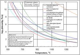
Even different formulations of glass have different viscosities and different rates of softening with temperature increases.

How does viscosity apply to us?

Although viscosity is of major importance to the manufacturer, it does have some relevance to kiln formers too.

Understanding that glasses have different viscosities – most often referred to as hard and soft – can help in the choice of colours and styles of glass to combine. Some glass will spread more, and also allow other glass to sink deeper into the layer than others. It might help avoid combining extremely hard and soft glasses next to each other.

It should also help explain some results that were not planned. It may help in when thinking about uneven slumps.

It is important to recognise that glass chemistry is extremely complicated, and to see that the expansion characteristics have to be balanced with the viscosity characteristics as the two main elements in compatibility. There are others, of course, but these appear to the two main ones.

Wednesday, 18 September 2013

Bubble Reduction in Casting


There are several things that can be done to reduce the number and size of bubbles in casting.

  • Fire higher - to 830ºC instead of 815ºC - and soak for at least four hours. This allows more bubbles to rise to the top and burst. If there are still more bubbles than wanted, increase the soak time.

  • Stack the glass in the centre of the mould, allowing a few centimetres from the mould walls. This allows the glass to spread and flow from the bottom and up the sides, reducing the likelihood of trapping air. If you have more than one stack, keep the same space between the stacks as the mould walls.

  • Make sure that the way you stack the billets or casting plates so there is a smaller space at the bottom of any cavity than at the top. The reverse allows the glass to soften and seal in the air in the space.

  • You can construct a mould to make billets of the general shape of the final object. This of course, is much more work, needing two moulds.

  • A major thing to avoid is the use of frit, especially at the bottom or deep in the mould as bubbles will collect around each piece and lead to a multiplicity of bubbles throughout the casting.

Wednesday, 11 September 2013

Thinfire as a Separator on Moulds


"I was told that it was possible to put a piece of thinfire paper under a circular piece of glass that is to be draped over a mould....  Has anyone done this or heard of doing it?"

Yes this can be done. Some caveats are in order though.

It is important to put a separator on the mould -normally kiln wash - before using it. Once coated, it will not need to be re-coated unless the surface is damaged, scratched, etc., for a very long time. If the kiln wash seems to be rough you can smooth it in various ways as noted in this tip.  The advantage of kiln wash is that it does not cost much and lasts a long time. The thinfire or similar is a one-time-use product.
The binder in the thnifire burns away during the heat up and allows the now unbound separator to drift down to the mould before the glass begins to conform to the mould. In that way it is very similar to a fine dusting of kiln wash powder over the mould surface before firing.
I don't see the point of using Thinfire or similar during slumps (although I can see that there are occasions where this method would be useful). For drapes, placing a bit of thinfire over the mould - especially if it is metal – is an additional precaution.

My view is that you have to kiln wash the mould anyway. KIln wash is cheap and long lasting while thinfire needs to be replaced after each firing.

Wednesday, 4 September 2013

Clearing Small Core Drill Bits


Core drill bits are very useful, as only a thin wall of glass is removed, leaving the main part of the hole as a single piece. This means that it is quicker than a solid drill bit through not having to remove so much glass. However, small diameter core drills often jam up with waste glass. This is evident when the drill ceases to drill through the glass, leaving a broad circular mark as it moves around on the glass.

Inevitably, at one time or another, the glass core will get stuck inside the drill bit. This needs to be cleared before any further drilling can be successfully done. It seems to be more common with the smaller diameter drills – from 5mm down.

The broken off core needs to be cleared from the back of the bit, not the diamond coated end. So you need to take the bit out of the drill and use a thin nail or piece of wire into the hole to push the glass out.

My collection of core drills.  At the front you can see copper wire and a thin punch for clearing blocked drills

Core drills need a more accurate means of steadying the bit than your hands. Imagine that you are trying to get that core out of the glass in tact. Any wobbling as you drill will break that core. When the core breaks, it is inclined to jam the cylinder. So a drill press is almost essential when using a core drill.

They also need water like any other drilling of glass. Normally this is supplied through the hollow core of the bit, which is beyond hand held drill motors.

For something as smaller than 3mm, a solid drill that removes all the glass rather than a core is more likely to be most successful. You can get diamonds bonded to piano wire that will give you holes from a fraction of a mm up to 2 or 3 mm and these can be used in dremel-like tools that take small diameter bits.

It is absolutely NOT recommended to use a core drill at an acute angle to start the hole. The wall of a 3mm core drill is very thin and easily damaged. It is ok to start a solid drill that way, but not a core drill.

There are a number of related posts beginning with this one which give advice on the many ways to drill holes in glass.


Wednesday, 28 August 2013

Finger protection

Grinding lots of glass pieces often leads to a number of small cuts on the tips of your fingers. There are several things that can be done to reduce these cuts and the tenderness that comes from lots of grinding.

The first thing is to take the sharp edges off the glass. You can do a simple, light grind all the way around the piece. This removes the extra sharp edges that often remain after breaking the glass.


You can go a step further and do a light arris around the piece. This is just lightly holding the glass at about 45degrees to the grinding bit and going all the way around on all sides. This does not take off the shape of the piece, but gives a more rounded feel to the piece.

Illustration of the effect of holding the glass at an angle to the grinding head - not so much needs to be taken away as in the illustration to get the effect

It is not generally recommended that you wear gloves around rotating machinery. There is too much risk of injury, even on a small grinding machine. Some of the alternatives to gloves include plasters (band aids), masking tape, electrical tape.

Other purpose-made things you can buy include rubber finger protectors, finger tip pads, finger caps (as used in counting money).


Other tools are made to hold the glass such as the grinder cookie


and Nick's Grinder's Mate 


Wednesday, 21 August 2013

Reclaiming Solder


Re-using solder can range from simply soldering the ends of the solder sticks together (if you are using blowpipe solder). This will then form a useable stick with solder blobs on its length.

If you have a number of blobs and splashes, don't throw them out. Collect them together and when you have enough you can make them into another stick of solder.


You can tape two narrow pieces of glass onto a length of marble or heavy steel about 3-4 mm apart. Put the pieces in the channel formed by these two pieces of glass and melt the pieces with your soldering iron. This will form a useable stick.

Lifting the new solder stick from the wood


The same can be done by cutting out a 3mm wide and deep channel in a piece of timber and doing the same as above. The wood will smoke a bit and blacken, but not ignite.  And you can use a blowtorch to melt the solder if you do it this way.


Using the (slightly irregular) solder stick


Thursday, 15 August 2013

Assembling Foiled Pieces

Keeping foiled pieces together while assembling them prior to soldering is sometimes a problem.

If the panel is rectangular - or at least one with multiple straight sides - you can use short battens of the length of the sides. Nail or screw them down to a board so that about one half of the panel is contained. So if it is a rectangle, two sides will be enough. If it is six-sided ,three pieces would do.


An assembled piece illustrating the two battens - although with a leaded panel

For ease of assembly, a copy of the cartoon should be fastened to the board first and then the battens fixed on top of the cartoon. The pieces can then be placed against battens and held there with pins or nails until the next pieces are ready.
Illustration of the cartoon fixed by the surrounding battens

Some prefer to tack solder the pieces together as they foil. This can be done in combination with the use of battens. However, leaving the soldering iron idling while foiling and using it only occasionally is very hard on the iron's tip and your electricity bill. I prefer to assemble the whole and then solder all at once.

Illustration of placing pins all the way around an oval panel

For circular or irregular shapes a slightly different approach is required. You can use multiple pins or nails along the perimeter to hold the foiled pieces together. An alternative is to cut a piece of scrap window glass to the shape of the external perimeter of the panel. Hold it is place with nails or pins and proceed as with a rectangular shape.

Placing nails all the way around an irregularly shaped piece

Saturday, 10 August 2013

First Ramp Rates

There is a lot of literature about annealing and cooling rates, as they are the most critical elements in producing a piece with minimum stresses within it.  But there is not so much information on initial ramp rates.

It is possible to break the glass by heating it up too fast during the initial temperature rise.  How fast you can increase the temperature is dependent on how even the heat is within your kiln and the profile of the glass.  Any suggestions have to be tested within your own kiln and setup rather than relying exclusively on others' experience.  Some of the considerations relating to the kiln are given in this blog about initial rates of advance.

So with those precautions, I put forward a suggestion based on my experience and information gleaned from the Bullseye site, education section and from Graham Stone's work. These lead me to suggest that the initial rate of advance can safely be the same as the second cooling segment as listed in the Bullseye chart Annealing Thick Slabs (Celsius and Fahrenheit). This ramp rate applies up to the softening point of the glass.

Experiments have shown that an evenly thick piece of glass 6mm thick cooled at 150ºC/270ºF per hour during the second cooling segment - can also be fired up at the same rate. And by extension:
  • A 12mm thick piece could be taken up at 99ºC/178ºF per hour
  • A 19mm piece could have an initial rate of advance of 45ºC/81ºF per hour
  • A 25mm thick piece of glass could be taken up at 27ºC/49ºF per hour.
These rates depend on a number of factors:
  • how the glass is supported,
  • the nature of the shelf,
  • the composition of the mould, and
  • the kiln characteristics as well as
  • the colour combinations and
  • whether the piece is tack fused or full fused.
Slower rates of advance are indicated if  
  • the kiln is side fired or has cool spots.
  • the shelf has not supported on 25mm/1" kiln posts.
  • the piece is tack fused, you need to slow the ramp rate by half.
  • there are strongly contrasting colours next to each other   

Remember that these numbers can only be used as a guide in conducting you own experiments.

More information is given in the eBook Low Temperature Kilnforming available from
and Etsy

Monday, 5 August 2013

Fusing with Painting


Combining Painting and Fusing

Painted oyster catchers with frit and stringer

It is possible to combine glass painting with fusing. Tracing paints are generally powdered iron rust and fused to the glass by the glass powder that carries this pigment. So it is possible to paint and fuse a project at the same time without loosing the intensity of the paint.

In general it is best to work down from the highest to the lowest temperature in your firings. This does require planning of the firing sequence in addition to the usual design considerations.

This sequence of firing depends on the glass stainers' paint you are using. The tracing paints (blacks, browns, some whites, some blue greens) that fire at 650ºC and above can be fired up to around 800ºC without losing much of their intensity. If you use Debitus paints, they can be fired to 850ºC without loosing their depth of colour.

Fused, painted and slumped piece painted both at fusing and slumping operations
If the paint is under glass pieces or under frit, the paint will appear to spread and the lines thicken. This is due to both the lens effect of the covering glass and the weight of the glass over the lines. If you require the lines to be of consistent thickness, you probably should paint after fusing.

You can, of course, use low firing ceramic glazes as they mature in the region of 700ºC to 850ºC. These can be painted on to the unfired glass and taken to full fuse without any fading. You do need to make sure the glaze has time for any volatile materials to burn off, so a slow rate of advance up to the slumping temperature of the glass is advisable.

Painted and fused, then painted and slumped.  Note the paint lines and coloured glass do not always match or need to.

If you are using glass stainers' enamels, you need to fuse and shape before firing. You can fire in the mould for the enamel firing as the temperature range is in the 520ºC to 580ºC range and will not add more mould marks to the glass. Keeping the glass in the mould protects against any tendency for the glass to alter shape.


Tuesday, 30 July 2013

Moulds for Bottles

One of the many styles of commercially prepared moulds


An alternative to buying moulds for slumping bottles is to use a sand bed. You can place the bottle into the sand and roll it a little from side to side to create a depression in the sand that then becomes the mould.

I use a fine sand (not builder's or garden) and coat it with alumina hydrate (slaked alumina). I use about 1 part alumina to 5 sand, but the mix is not critical, just enough alumina to coat the sand particles. It can go directly on your kiln floor if you have an easy way to pick it back up, as it is re-usable. Or you can put it in a stainless steel tray or any open topped box that will withstand the temperature.


Make your depressions and then sprinkle or sift a fine layer of alumina over the area - I use an old sock to hold some and dust it over the sand. Then lay the bottle in the depression.

The amount of sand impression you get is dependent on the temperature you use - the higher, the more sand texture you get. 

This way of slumping bottles eliminates the need for a mould and it is variable for different sized bottles.