Sunday, 27 February 2022

Inhibiting Bacterial Growth with Bioactive Glass


Inhibiting Bacterial Growth with Bioactive Glass

Posted  on 


Computer rendering of bacterial culture

Despite numerous advances in technologies, bacteria remain a cause for concern in both clinical and industrial settings. They pose an especially challenging problem in medicine where only bactericidal strategies which have a minimal detriment to human health are feasible, and bacterial infection continues to be a leading cause of morbidity and mortality.

Surgical procedures in particular are associated with an increased risk of infection, and infection is the most frequently encountered post-surgical complication. The primary means of prevention and treatment of bacterial infections is the administration of antibiotics. However, the power of antibiotics in the fight against infection is diminishing as strains of potent bacteria are developing multi-drug-resistance.

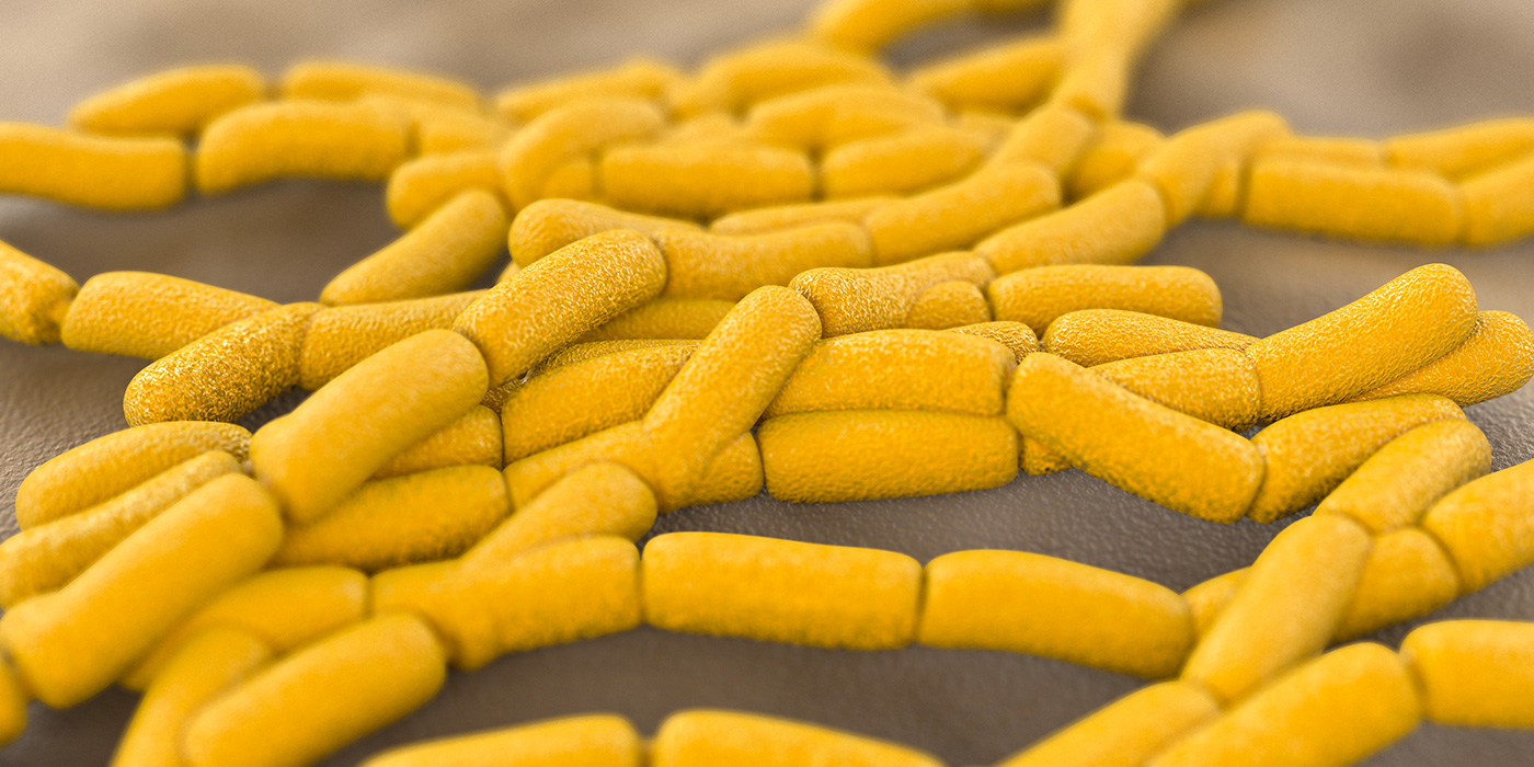
In contrast to historical beliefs, it is now apparent that the majority of bacteria live in surface-bound microbial communities, rather than as free-swimming entities. On binding to the surface, bacteria secrete adhesion proteins that provide an irreversible attachment. The bacteria proceed to proliferate and create a colony that ultimately results in the formation of a mature biofilm protected by a peptidoglycan envelope.1 Such biofilms account for over 80% of clinical microbial infections, and so are associated with considerable morbidity and expense.2

In addition to the possibility of biofilms containing antibiotic-resistant strains, the bacteria are protected from antibacterial agents and the body’s immune system by the peptidoglycan envelope. Biofilm-associated bacteria are 100 to 1,000 times less susceptible to antibiotics than free-swimming bacteria, and so patients with biofilm infections are rarely cured by treatment with antibiotic agents, which are used nonetheless due to the lack of alternatives. Furthermore, there is the scope for bacteria to leave the biofilm and colonize other areas throughout the body.

Consequently, there has been much research in to the development of new broad-spectrum antibiotics and also novel antimicrobial strategies.

Novel antimicrobial materials

Nanotechnology has opened up the potential for the development of new types of materials with antimicrobial properties. It allows the physicochemical properties of a material to be changed in order to achieve antimicrobial effects.3

Antimicrobial nanomaterials include a wide range of metal, metal oxide, and organic nanoparticles and so have numerous modes of action. Although a range of chemical interactions are involved, the end result is membrane damage that leads to loss of integrity and impaired metabolism and ultimately cell death.

The advantage of nanoparticles over antibiotics is that their efficacy depends solely on contact with the bacterial cell wall; they do not need to enter the cell. Consequently, their lethal effect is exerted irrespective of the specific genetics of the target bacteria and is unaffected by the resistance mechanisms used by bacteria to evade antibiotics. Furthermore, the large surface area to size ratio of nanoparticles means that high activity can be achieved with a small dose, whereby minimizing the risk of toxicity. It is therefore hoped that nanoparticles may provide an effective alternative to antibiotics for the treatment of both free-swimming and surface bound bacteria.

Nanoparticles could be used in antimicrobial treatments and in the manufacture of nanocomposite products suitable for use in medical materials and devices.

Bioactive glass

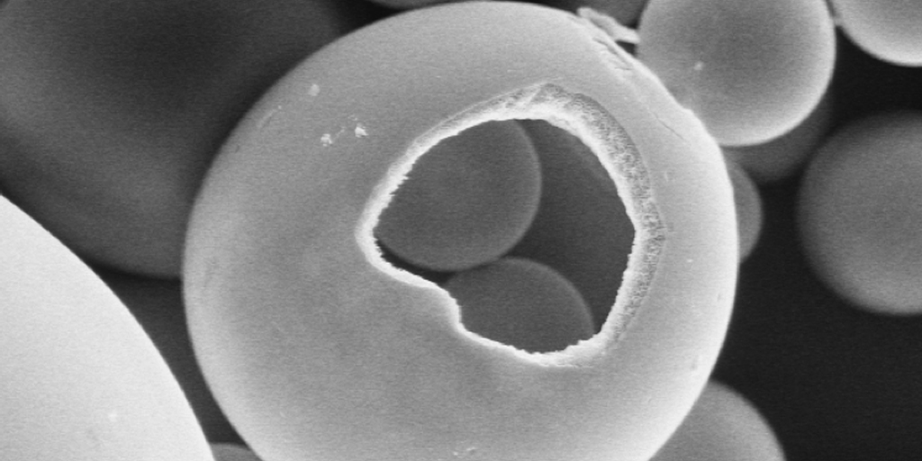
Bioactive glass is a type of glass made from high-purity chemicals, such as silicon oxide, calcium oxide, and phosphorus oxide, that induces specific biological activity.4 Furthermore, by modifying the composition and structure of the glass, its physical properties can be tailored to meet a specific need.4

Bioactive glass elicits a negatively benign immune response and has been widely used in a range of biomedical applications, including tissue engineering, bone grafting, dental reconstruction and wound healing.5 It is able to bond to either hard or soft tissue and has been shown to facilitate strong new bone growth, promote soft tissue regeneration and enhance vascularization to ensure a healthy blood flow to the newly regenerated tissue.6–8 It has also been mixed with dental filling materials to promote the remineralization of dental caries.9

In addition, borate bioactive glass has been shown to have antimicrobial properties against a wide range of bacteria, including MRSA and E-coli.10 It has been shown that bacteria are unable to adhere to bioactive glass and so microfilms cannot develop on its surface.11 This is supported by clinical observations; no infections have been reported on bioactive glass implants.11 In addition, the inclusion of bioactive glass into dental filling material reduced bacterial penetration by 40%, whereby reducing the rate of decay and increasing the lifetime of the restoration.12

The antimicrobial action of bioactive glass can be further increased, giving the glass a broader spectrum of antimicrobial activity, by the addition of ions such as silver, yttrium, selenium, and iodine.13

The use of bioactive glass fibers to promote wound healing and soft tissue repair and the inclusion of bioactive glass in bone grafting and dental restoration composite materials to promote bone growth thus gives dual benefit — more rapid healing and reduced risk of infection.

Mo-Sci produces implant grade bioactive glass powders of varying sizes and with specific compositions suitable for mixing with composite materials.14

References

  1. Davey ME and O’Toole GA. Microbial biofilms: from ecology to molecular genetics. Microbiology and Molecular Biology Reviews 2000;64(4):847–867.
  2. Hall-Stoodley L, et al. Bacterial biofilms: from the natural environment to infectious diseases. Nature Reviews Microbiology 2004;2(2): 95–108.
  3. Karwowska E. Antibacterial potential of nanocomposite-based materials – a short review. Nanotechnology Reviews 2016;6(2):243?254.
  4. Brauer DS. Bioactive Glasses—Structure and Properties. Angew Chem Int Ed 2015;54: 4160–4181.
  5. Rahaman MN, et al. Bioactive glass in tissue engineering. Acta Biomaterialia 2011;7:2355?2373.
  6. Gerhardt L-C and Boccaccini AR. Bioactive Glass and Glass-Ceramic Scaffolds for Bone Tissue Engineering. Materials 2010;3:3867?3910
  7. Pugely AJ, et al. Influence of 45S5 Bioactive Glass in A Standard Calcium Phosphate Collagen Bone Graft Substitute on the Posterolateral Fusion of Rabbit Spine. Iowa Orthop J. 2017; 37: 193–198.
  8. Gorustovich A, et al. Effect of bioactive glasses on angiogenesis: In-vitro and in-vivo evidence: A review. Tissue Eng. Part B Rev. 2010;16:199?207.
  9. Chatzistavrou X, et al. Fabrication and characterization of bioactive and antibacterial composites for dental applications. Acta Biomater. 2014;10:3723–3732. Available at https://www.ncbi.nlm.nih.gov/pubmed/24050766
  10. Ottomeyer M, et al. Broad-Spectrum Antibacterial Characteristics of Four Novel Borate-Based Bioactive Glasses. Advances in Microbiology 2016;6:776?787.
  11. Zhang D, et al. Factors Controlling Antibacterial Properties of Bioactive Glasses. Key Engineering Materials 2007;330-332:173?176.
  12. Khvostenko D, et al. Bioactive glass fillers reduce bacterial penetration into marginal gaps for composite restorations. Dental materials 2016;32(1):73–81. Available at http://www.demajournal.com/article/S0109-5641(15)00437-6/pdf
  13. Xu Y, et al. Study on the Preparation and Properties of Silver-Doped Borosilicate Antibacterial Glass. Journal of Non-Crystalline Solids 2008;354:1342?1346.
  14. Mo Sci Corporation website. http://www.mo-sci.com/en/products.

Wednesday, 23 February 2022

Fused Glass Project Sheet


Why is a project record sheet useful?

Some kind of record helps to set down the client and maker agreements, estimate quantities, determine prices, review past practices for successes and record possible changes for the future.  

Even if you do not have clients, comparing the record sheets over a period can give you information on how quickly you work, the amount of glass you use in relation to size and complexity, information for costing, etc. It can give you confidence in stating - and sticking to - your prices.

These purposes are clearly different from a kiln log or firing record.  This is much more for assessment of elements for costing and pricing.  You can, of course, include this with your firing log or vice versa.

What should be included?

Desirable elements include the following.  You may have others to add according to your individual practices.  

Initial project information
·        Project description - including dated sketch or photo or reference to the cartoon.
·        Intended location – autonomous, primary glazing, encapsulated, attached, etc.
·        Dimensions for both two- and three-dimensional projects.
·        Delivery date. This may be an estimated or firm date.
·        Price or estimate – indicate which.

Materials and Equipment
·        Glass types and codes that you will (or have) used, in case additional glass is required.
·        Amount and cost of glass used during completion. This is not simply the amount used, but also the amount you did, or would require to, buy to complete the project.  
·        Glass separators – kiln wash, fibre paper, etc., including their cost.
·        Kiln use. The number and amount for each firing of the kiln should be added to account for maintenance, supplies, and depreciation.
·        Mould use.  A notional figure should be added for each use of a mould similar to the use of the kiln.
·        Miscellaneous materials including their costs.


Time
The time used to complete the project should be noted as you go along.  It can be divided into various process – such as cutting, firing, cold working, cleaning – or as a simple cumulative amount of time on the whole project.

Description of project results
A critique of the project including what might be done differently, the successes, the discoveries, should be written up at the end of the project.


What does all this record keeping provide me?
Recording this kind of information provides a record of how various projects went, how you met any difficulties, what the successes were.  This is useful to look back on when similar projects arise.

This information is invaluable in assessing materials costs, and time required for various styles and complexity of projects.  It enables a quick and assured way of estimating the costs of a project when a commission is requested.  It gives you assurance about your pricing and valuation of projects you have completed for craft fairs or friends. You don’t have to be apologetic about the price of items, because you know the costs.


A possible form might look like this:


Project information

Name of project:
Date:                           Clients:  
                           Contact details:


Due date:
Project title and description (photo?)


Dimensions  2D                           3D

Materials required
Glass descriptions:       
codes              quantities            costs


Miscellaneous materials:  
description        quantity             costs


Kiln firings:     #                           costs


Mould use:       #                           costs


Summary of Costs:                                 ____.__


Processes
The starting and finishing time, including any attention to equipment should be recorded for each working session on the project.  The actual hours and minutes can be added up later.  You can simply record the times for each project regardless of process, e.g.:
__:__  to __:__;  __:__  to __:__;  __:__  to __:__;

Or you can record by process, e.g.
Cutting and fitting glass.  
__:__  to __:__;  __:__  to __:__;  __:__  to __:__; etc.


Kiln preparation
__:__  to __:__;  __:__  to __:__;  __:__  to __:__; etc.


Cold working
__:__  to __:__;  __:__  to __:__;  __:__  to __:__; etc.


Summary of time:                                   __:__
Hourly rate * time = your pay
Your pay + costs = base cost * contingency % +profit = price


You will, of course, develop your own form of recording for your project materials, costs and time used.  But it is important to keep some record of what amount of effort and cost has gone into each project.  With the passage of time, things seem easier and less costly than they did at the time.  A record of the project reminds you of the actual costs, difficulties, processes and time.


Sunday, 20 February 2022

Enhancing Road Marking Paints using Spherical Glass Beads


Enhancing Road Marking Paints using Spherical Glass Beads

Posted  on 


Road markings make a vital contribution to road safety and optimizing use of road space and make it possible to provide information that it is not easy to convey using mounted signs.1 Furthermore, signage applied directly to the road surface provides a form of continuous messaging which can be seen when a verge-mounted sign may be obscured.

The effectiveness of road markings in enhancing the safety of road users depends on the markings being clearly visible. This becomes particularly important at times of low light, such as during night time, rain or fog. Since the visibility of road markings is a crucial factor in ensuring traffic safety, strict performance requirements have been introduced to ensure the efficacy of road markings, which must be checked and maintained on a regular basis. European reflectivity standards (European Standard EN 1436) stipulate the minimum levels of daytime and night-time visibility as well as color and skid resistance.3

Road markings come in a range of formats, including thermoplastic, screed, spray, extrusion and ribline, but all must meet strict visibility requirements.

Improving the Visibility of Road Markings

Recent collaborative European research has determined the minimum distance at which road markings should be visible to drivers to be equivalent to two seconds of travel time.5 The distance from which a road marking is visible depends on a variety of factors.4,5 Many of these are driver-related, e.g., the driver’s vision, car cleanliness, headlight strength; or unavoidable, e.g., glare from oncoming vehicles, rain. The composition of the road marking however can be designed to optimize its visibility in a range of conditions. For example, titanium dioxide pigment is used to maintain the bright color of road markings and crystallized titanium dioxide is added to prevent the build-up of dirt on markings, which would reduce their visibility.

Most of the light emitted by the headlights which hits the road surface is reflected forwards or absorbed by the road surface itself with only a fraction of the light reflected back towards the driver’s eyes. The reflecting of light back in the direction of the light source is known as retroreflection.5,6 The higher the coefficient of retroreflected luminance the greater the contrast between the road marking and the road surface. The more of the light from the headlights that a road marking reflects back to the driver, the more visible the road marking will be, especially at night and in bad weather.

Titanium dioxide and other such additives do not create retroreflection to enhance the luminescence of road markings. In contrast, the addition of glass beads increases retroreflection, whereby improving the night-time visibility of road markings. The headlight beam penetrates the glass bead, hits the pigmented road marking, and is reflected back towards the car driver. The road marking therefore appears to light up and so the visibility of the road marking is increased significantly. Road markings incorporating high performance glass beads are five times brighter than road markings that do not.

The extent of retroreflection achieved by glass beads depends on the size of the beads and the quality of the glass. The level of retroreflectivity is determined using the 30-metre geometry. This is the amount of reflected luminescence at an illumination distance of 30 m, a driver height of 1.2 m, and a headlamp height of 0.65 m.7 A minimum retroreflectivity of 120 mcd/m2/ lux on a dry surface is recommended.

Glass Beads – Road Marking Enhancement

Glass beads for use in road markings typically have a refractive index of between 1.5 and 1.9. They are produced in a variety of sizes ranging from 100 to 1500 microns in diameter and with varying degrees of roundness. Glass beads can be mixed into the road marking material during production (intermix beads), added as the road marking is applied (injection beads) or applied to the surface of newly applied road markings before they have set (drop-on beads).

The beads must be embedded by at least 50% of their diameter to ensure that they do not become dislodged. However, increasing the degree of bead embedment reduces the level of retroreflectivity, so an effective balance needs to be achieved. It is inevitable that some of the beads will become covered with the marking material but this will soon be rubbed off by passing traffic.

The quality of the retroreflection produced by the glass beads also depends on the size and roundness of the beads, the amount of beads added to the road marking and the viscosity of the road marking material. Highest retroreflective performance is achieved using the larger beads with smoother, more round surfaces. An effective distribution level of glass beads is 400 to 600 grams per square meter of road marking.

Mo-Sci Corporation produces glass spheres for a wide range of applications.8 Mo-Sci supplies high quality glass, which can be customized to meet specific project requirements. They produce glass beads suitable for increasing the visibility of road markings to tight specifications that guarantee optimum reflectivity.

Conclusion

Road markings are an essential safety feature. Glass beads significantly increase the reflectivity of paints on the road, which in turn significantly improves their visibility and consequently driver and pedestrian safety.

Glass beads are the only road marking additive that causes retroreflection, sending more of the headlight beam back to the driver. Consequently, glass beads make road markings at night time appear five times brighter than road markings that do not contain glass beads.

References & Further Reading

  1. Department of transport UK 2003. Traffic signs manual Chapter 5 Road markings. Available at https://assets.publishing.service.gov.uk/government/uploads/system/uploads/attachment_data/file/223667/traffic-signs-manual-chapter-05.pdf
  2. Charlton SG, et al. Using road markings as a continuous cue for speed choice. Accid Anal Prev. 2018;117:288?297. doi: 10.1016/j.aap.2018.04.029. Epub 2018 May 9.
  3. Highways Markings. A Guide to IS EN 1436 European Standard for Road Markings. Available at http://www.highwaymarkings.ie/documents/is_en_1436_1.pdf
  4. Owens Da, et al. Effects of age and illumination on night driving: a road test. Hum Factors 2007;49(6):1115?1131.
  5. The National Cooperative Highway Research Program. Chapter 3. Available at http://onlinepubs.trb.org/onlinepubs/nchrp/nchrp_syn_306_22-37.pdf
  6. Stoudt MD, Vedam K. Retroreflection from spherical glass beads in highway pavement markings. 1: Specular reflection. Applied Optics 1978;17:1855?1858.
  7. Pike AM, et al. Evaluation of Retroreflectivity Measurement Techniques for Profiled and Rumble Stripe Pavement Markings. Transportation Research Record 2011. Paper 11-1293. Available at http://docs.trb.org/prp/11-1293.pdf
  8. Mo-Sci Corporation. Company website available at http://www.mo-sci.com

Wednesday, 16 February 2022

Never refuse to refuse?

“Never refuse to refuse” is a statement often seen on social media. 

I object.

If the saying were changed to “never refuse to re-use” maybe I would agree under certain circumstances.

Before you even begin to think about using the broken or disappointing glass, you need to determine what went wrong.  The difficulty may prevent you using it in certain ways, or even at all. 

You need to determine if the break is due to incompatibility.  If it is, you cannot refuse or reuse it in any way.  It will continue to break anything you combine it with.  It must be junked. This means you need to have a way to diagnose the cause to the stress that lead to the break.

If you are certain the break is from thermal shock or inadequate annealing, it is possible to combine the pieces with other glass.

It is essential to determine why the problem occurred to know whether you can re-fuse.  You also need to know, or discover, how to prevent the break for the future. Once the cause of the difficulty has been determined, it may be possible to fuse again, but consider what the appearance will be.  The nature of the difficulty will give you clues to re-usability.

A repaired piece most often shows it is repaired. To try to appropriate the Japanese art of repairing the revered but broken object, just does not work for a broken new piece.  It was a new piece, with no history of use or display.

The phrase “never refuse to refuse” – while catchy – is extremely misleading and can lead to a lot of difficulty. Learn the lessons and move on to make a whole new and sound piece, rather than a repaired piece. 

Sunday, 13 February 2022

Using Porous Glass Microspheres for Targeted Drug Delivery


Using Porous Glass Microspheres for Targeted Drug Delivery

Posted  on 

linkedin sharing button Share
twitter sharing button Tweet
facebook sharing button Share

Porous hollow glass microspheres

Finding methods for improving efficiency and bioavailability is central to targeted drug delivery. While controlled release dosage medication forms are the norm, they can encounter many limitations. One disadvantage is the difficulty of locating and retaining the drug delivery system within the gastrointestinal (GI) tract due to gastric emptying variation.1 This can cause drug release that is insufficient for the patient or result in shorter residence time of the dosage in the stomach. 

To increase gastric retention and improve drug absorption, hollow microspheres have been developed and applied in the clinical setting for certain patients.2 Porous-wall hollow glass microspheres used in medicine are often produced from biopolymers, ceramics, bioactive glasses, and silicates. Hollow microspheres feature a 10 to 100 micron-diameter hollow cavity for the containment of certain substances.3

The most predominant mode for drug administration to the systemic circulation is the oral route. Some drugs have difficulty absorbing through the GI tract when using this route, prompting professionals to seek alternative methods for delivering pharmacologically active substances to the body.

The porous or hollow features of microspheres offer the ability to encapsulate fragile drugs and provides protection from biological compounds that may interfere with drug availability.4 These spherical, empty particles can remain in the gastric region for long periods of time and extend residence time of drugs in the GI tract.

Porosity offers improved loading efficiency and helps control the release of medications. Overall, hollow microspheres improve bioavailability of a drug, thereby reducing drug waste.

Microspheres can be produced to feature a uniform shape and size that can improve delivery of spheres to a specific target site. Additionally, microspheres are an ideal candidate for carriers of therapeutic agents due to their porosity, large surface area, and volume.

The hollow center of the microspheres reduces their density to such a degree that they have the potential to be buoyant. This behavior makes hollow microspheres suitable for use in a wide variety of applications.

Advantages of Porous Glass Microspheres

Hollow microspheres can reduce dosing frequency, allowing for improved patient compliance. Also, a desirable plasma concentration of a therapeutic agent can be maintained with microspheres by continuous drug release. The structure of the microspheres also results in an increase in gastric retention time, meaning therapeutic agents are released over a longer time. Other advantages of hollow microspheres include:

  • Site-specific drug delivery to the stomach
  • Sustained release effect helps avoid gastric irritation
  • Short half-life drugs can achieve a better therapeutic effect

Limitations of Porous Glass Microspheres

Patients are required to consume a large amount of water for hollow microspheres to float and function. Instead of merely taking a sip of water with a drug (typical of the oral route of medication administration), patients must drink a full glass (200 to 250 ml) of water with the microsphere. In addition, hollow microspheres are unsuitable for drugs that feature stability and solubility issues in gastric fluids.

Savannah River National Lab (SRNL) and Mo-Sci Microspheres

The SRNL has teamed with Mo-Sci Corporation, experts in the production of specialty glasses, to create porous wall, hollow glass microspheres that consists of glass “microballoons” smaller than the diameter of a human hair.

SRNL’s microspheres feature a unique network of interconnected pores in the walls. These pores allow tiny “microballoons” to be filled with gasses as well as other materials. Each SRNL microsphere is around 50 microns in diameter, and the walls are around 10,000 angstroms thick. The walls feature pores that come to about 100 to 300 angstroms. Each pore allows gasses to entire the spheres and be stored or cycled on absorbents. 

The original use for SRNL’s microspheres was to provide a solid-state storage method for hydrogen. Further research, however, has revealed their powerful utility and practical application in medicine. Currently, Mo-Sci plans to offer SRNL’s porous-walled hollow glass microspheres as a transport system for targeted drug delivery, among other uses. 

Microspheres are being further investigated in an effort to discover new applications within healthcare. While further study is ongoing, microspheres will hopefully provide enhanced patient care and improve the effectiveness of medication delivery across a broad range of disease states.

References

  1. Kurrey A, Suresh PK, Singh MR. Hollow microspheres as a drug carrier: An overview of fabrication and in vivo characterization techniques. Chronicles of Young Scientists. 2014;5(1):1-10.
  2. Qing W, Wenhai H, Deping W. Preparation of hollow porous HAP microspheres as drug delivery vehicles. Journal of Wuhan University of Technology-Mater. Sci. 2007;22(1):174177.
  3. Hossain KMZ, Patel U, Ahmed I. Development of microspheres for biomedical applications: a review. Progress in Biomaterials. 2015;4(1):1-19.
  4. Li S, Nguyen L, Xiong H. Porous-wall hollow glass microspheres as novel potential nanocarriers for biomedical applications. Nanomedicine. 2010;6(1):127–136.
  5. Wicks GG, Heung LK and Schumacher RF. Microspheres and Microworlds. American Ceramic Society Bulletin, Vol. 87, No. 6
  6. http://www.mo-sci.com/porous-silica/ 

Wednesday, 9 February 2022

Frosting on slumped glass

 [We’re] Having a few challenges with a stainless-steel S-curve mould (15cm x 10cm [prepared with boron nitride]. … When we slump a piece of glass, we get a frosted effect … in places where the glass was touching the mould at the beginning. I don't think it's devitrification, because the glass itself isn't cloudy, it's just hundreds of little bumps and dimples.

Photo credit: Adrian Cresswell


 This is a mould that combines draping and slumping in the same firing. The glass must drape over the hump and slump into the valley at the same time. This is effectively two processes in the same firing. It does require some compromise in scheduling as a result.

 The evidence presented shows boron nitride – a slippery surface – was used to prepare the mould. In another firing Thinfire – a powdered surface – was used as a separator. Both created this marking on the back. The schedule was not presented.

 This indicates something other than the separator is creating the problem. Note that the marking also occurs at the extreme right end where the glass would be resting on the lip of the mould. The marking does not occur where the glass is slumping down into the curve. It only occurs where the glass is draping.

 As suggested, this is not devitrification. That occurs on the surface rather than on the bottom. This further indicates the difficulty is between the glass and the mould.

 I suggest the marks are from the glass sliding along the mould. These are frequently called stretch marks. The glass is sliding and stretching along the mould. This blog post contains much more information.

 It is of course possible that insufficient boron nitride was placed on the steel and the glass grabbed the steel. It is worth checking, although I don’t think it likely.

 You might think the Thinfire covering of the steel would make everything smooth. However, Thinfire turns to powder and fibreglass particles after about 400°C/753°F. These particles are drawn along as the glass moves against the mould. The particles can bunch and remain as bumps on the surface of the mould. This may account for the rougher surface with Thinfire than boron nitride.

A summary

These stretch marks occur when the glass moves excessively against the mould. This is usually a combination of high temperature and fast ramp rates. Slumping should be done at the lowest practical temperature. The soak should be long, rather than brief.

The Remedy

 Fire more slowly and to a lower temperature. The Bullseye suggestion from their quick tips is for a double curve (or wave) mould of 250 x 210 x 40 mm (9.85" x 8.25" x 1.6"). They suggest a ramp rate of 167°C to 660°C /1221°F with a soak of 10 minutes for a 6mm/0.25” thick piece.

 In my experience this is too fast. Slumping into this mould can be done at 630°C/1167°F with a 30-minute soak in my kilns using the same ramp rate.

 This is a simple mould to slump and drape into. It is essentially two partial cylinders pushed together in opposite directions. The curves are gentle and progressive. There are no sharp changes of direction. These factors mean that the slow and low approach will work well.

 However, in this case the curves will be even tighter as the full length is 150mm x 100mm/ 6” x 4”. The height is not given, but for a self-standing piece, it likely to be a minimum of 40mm/1.6". This makes for a tight curve on the mould. It is likely the glass will slide more than on a gentle curve. My thought is that the steel mould has been produced without knowledge - or testing - of the practicalities of getting the glass to bend to such a small radius. This means that I would be trying a schedule of about 125°C/225°F per hour to a top temperature of about 630°C/1167°F with a 1.0 to a 1.5-hour soak. The glass is going slump much more slowly with this smaller span.

 With gentle heating -slow ramp rate, long soak - the glass gradually conforms to the shape of the mould without stretching over the hump/crest of the mould. Instead, what happens is that the glass slips slightly from the opposite end of the mould. To counteract this, I place the glass 6mm/0.25” over the upraised end of the ceramic mould. This then finishes just inside the mould’s edge.

 With a steel mould, this is not possible without the glass hanging up on the hot and sharp edge. The glass will need to be at the edge or just inside to prevent hanging up on the end of the mould. The glass will slip down the mould a little, but not so much as to cause problems. It is possible to prop a piece of fibre board at the upturned end of the wave mould to support the overhanging glass if the full curve is required.

 The glass on the high part of the mould will not stretch at the low temperature, but gradually conform to the shape of the mould.

 I have much more information on this and other things in the eBook:

Low Temperature Kilnforming; an Evidence-Based Approach to Scheduling


Fitting Glass in Leading


Even though you think you have cut the glass exactly to size, it always seems that some adjustment is needed to areas of a piece to fit both into the lead came and be within the lines of the cartoon.

The temptation is to trim the glass to the amount of overlap of the cartoon line.


Note the extent of the overlap of piece #7 on the right.

In the above photo it would seem to be easy to just trim the straight line off the piece.  If you look carefully at the left side of the piece, you will see a gap between the glass and the lead came.  This means something more is happening than just being too large.  If you were to cut the glass down to fit within the cartoon line at this point you would find it too small in the end.

To find out what is going on underneath the lead came, you will see that I have made a line with a felt tip pen at the edge of the came.


When pulled out from under the came the line shows there is more glass under the came at the lower left than the middle left.  This indicates that the lower left needs to be adjusted rather than the right edge.


Groze or grind the glass to an even amount of glass between the felt tip line and the edge of the glass. This may have to be done several times to get the proper fit.  In this case I used the grinder because of the extreme texture of the glass.


This photo shows the glass fits at the bottom right, but needs more adjustment at the top right.  But it does fit under the came at the left side now. The amount of adjustment can be judged by marking the glass and grinding a portion away to fit.


An alternative example of the advantages of checking the glass is fully fitted within the came is shown here.


Here the blue piece shows it is slightly too large at the top.  The temptation is to refine the edges and reduce the size slightly.  Before doing that, it is advisable to check on how the glass is fitting into the came.  Again, run a felt tip marker along the edge of the came before pulling it out to adjust the size.


This shows there is a little bit of glass not broken off at the left side of the bottom tip.  Also, there is a larger space between edge and felt tip mark on the right than the left.

The first thing to do is to take off the excess glass on the lower left of the bottom tip and try the piece again.  That may be enough to allow the glass to fit into the came and match the cartoon.


The excess glass was ground away and a little taken from the bottom right side too.


This shows that just removing that small piece of glass has allowed the blue piece to fit correctly into the came and to fit the next piece of came to be placed without causing the panel to grow in size.


When a piece of glass is too large in leading, you need to check that it is fitted properly within the came, before adjusting the outer edges.  A method to do this accurately is described.