Among the
many ways of making frit, using thermal shock can be a simple way of producing
significant quantities of frit.
The process:
Clean the
cullet well. It is not important to dry
it as that will happen in the kiln.
Place the cleaned glass in a stainless steel container. Take the temperature up to at least 300C as
fast as you like – the glass is going to be fractured anyway.

The cullet in stainless
steel bowl
360fusionglass.blogspot.co.uk
While the
temperature is rising get a bucket or basin of cold water to place very near
the opening of the kiln. When the kiln
has reached the temperature, switch off and open the kiln. Reach in with heat resistant gloves and pull
out the container. Tip all the glass
into the water. It will steam and
crackle, but no damage will occur, even to a plastic container.

The heated frit in
water
360fusionglass.blogspot.co.uk
When the
glass is cool (a few minutes) drain the water off and dry it, either in the
kiln or on top or spread out on newspaper.
After the glass has dried you can break it up further with your hands,
or any of the other ways of smashing glass into frit.

The fractured glass
after drying and before breaking
360fusionglass.blogspot.co.uk
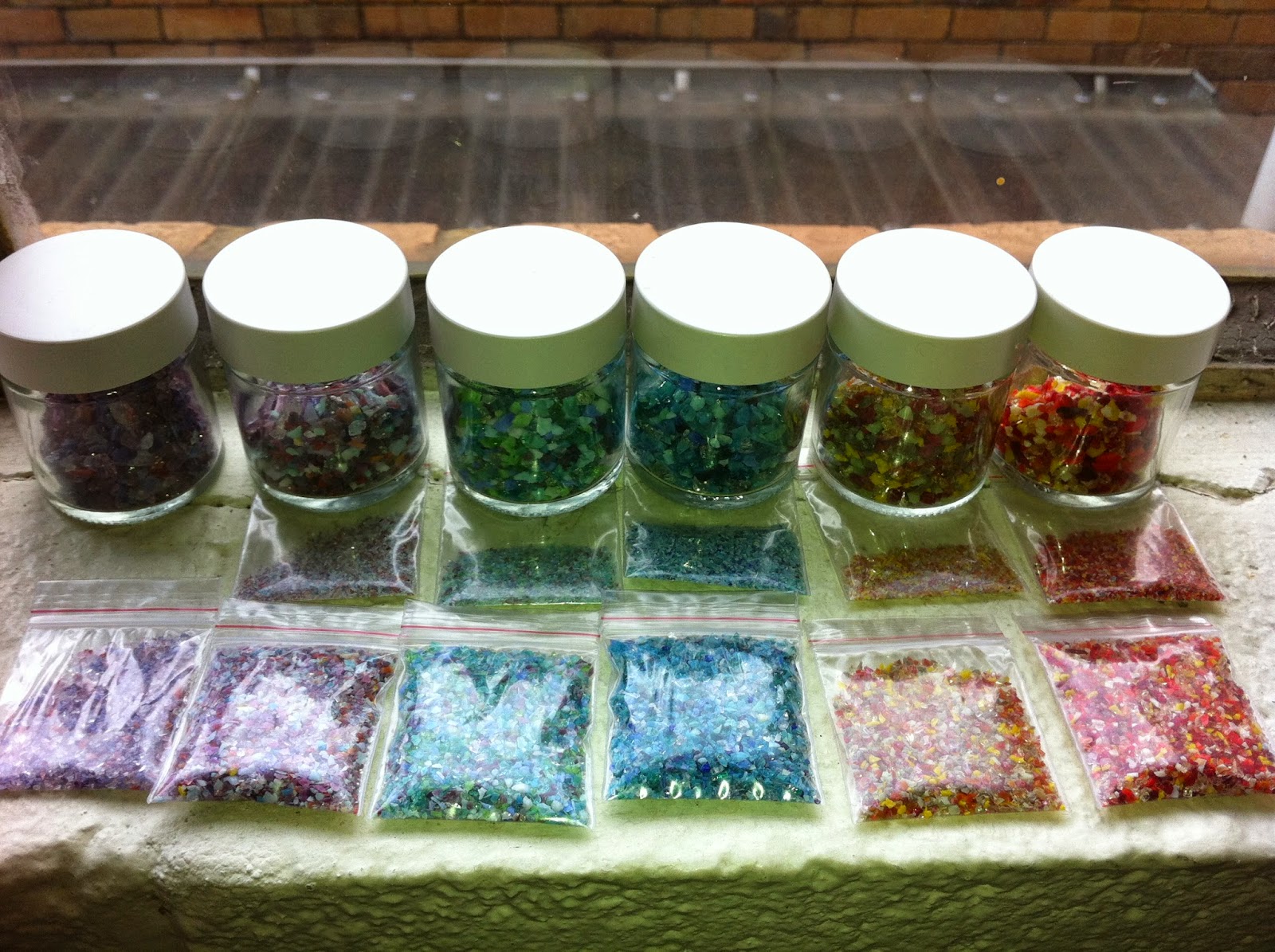
Fritting:
Break up the crazed glass with your usual method of creating frit, and sift it through graded seives before cleaning any contaminants from the frit.

Cleaning:
My practice is to discard all
of the very fine frit and powder resulting from this smashing process, as it is likely to be contaminated
with other things, which can give a grey appearance to the work.
However, you can use strong magnets to remove steel particles from the glass frit and powder. Some have recommended the use of the magnetic trays used by car mechanics to help remove the steel contaminants. In both cases, the magnets should be covered in plastic to make cleaning of the magnets easier. You simply take the plastic off the magnet or tray and shake the residue off the plastic, leaving an uncontaminated magnetic surface.
The magnets will not remove non magnetic materials such as a range of stainless steels, and other non ferrous metals. This requires you to use metals that can be magnetised as your breaking implements. Also, magnets will not remove other non metal contaminants. This means it is important to clean the glass well at the start of the process and keep it clean throughout the breaking process.