Showing posts with label Leaded Glass. Show all posts

Friday 18 May 2018

Leading Small Circles

Putting came around small circles such as lenses and small bullions often leaves an irregular curve. There is a way to avoid this.

Use oval or round came to reduce the kinking of the leaves of the came. As there is less material at the edges of the leaves of oval came, there is less kinking than on flat came, where the thickness of the leaves is constant.

Begin to form the lead round the circle, about half way. Then take the circle out of the came and cut, at a right angle to the length of the lead, at an angle from top to bottom. The degree of the angle is not important at this stage, only that you can repeat the angle – so it must be fairly shallow and natural for you.


Put the circle back into the came and continue to form the came round it until you meet the angled cut at the beginning. Again at right angles to the length of the came, cut a repeat of the angle.


Then fold this end toward the other end. Push the two angled ends together. If they slip up and down from each other, the came is too long. Open the came and cut a sliver off.


Try again until they meet with very little “slippage”.


Then the piece is ready to put into the panel. Place the join at a lead joint so you don't have an additional solder spot.


This technique can be used for small ovals too.

Friday 11 May 2018

Leading Procedure

Cut the leads exactly as the cartoon indicates. In other words, where one line runs into another, that is generally a stopping/starting point for the came.


Always lead to the cartoon line, not the glass. This ensures accurate completion of the panel. If the glass is slightly too small, the cement will take up the gap (assuming the flange of the came covers the glass – if not, you need to cut another piece of glass that fits). If the glass overlaps the cut line, it needs to be reduced.  A description of the process is given here.

This shows the use of a guage to determine where to cut the horizontal lead came.


Cut the ends of the came shorter than the glass. The best way to determine this is to place a piece of came of the dimensions being used for the next edge on the cut line. Use it to determine the length and angle for the cut. The object is to have each piece of came butt squarely against the passing came, to make a strong panel and to make soldering easier.

Leading - Establishing the perimeter

The first thing to be established about the panel is the placing of the came that goes around the edge of the panel.

Fix your cut line cartoon to the work board.  Usually a long strip of masking tape on all the edges will be sufficient.  To establish the placing of the battens, which will form the frame for the leading process, you need to determine the spacing from the cut line.

This shows the initial battens in place and ready for the final two battens to be put in place before soldering.

To determine the size of the off-set of the battens you should cut a short piece of the came you will be using for the outside and use that as a guage.  Place the heart of the came on the outside cut line near one end and move the batten to the side of the came.  Nail that end of the came to the board.  Move the guage came to the other end of the cut line and do the same with the batten as you did for the other end.  Establish one other batten at right angles in the same way.  Then you are ready to place the cames.

Make a straight cut across the came to be used for the outside and put that trimmed end into the corner and along the vertical wood strip. The lead should extend beyond the cut line to accommodate the length of the upper horizontal came. The minimum length must be longer than the width of the perimeter came that will butt against it. If it is even longer, the extra can be trimmed off after the leading is complete or after soldering.


Next butt a trimmed piece of perimeter came along the horizontal wood strip. This one should be shorter than the cartoon. It should be half the width of the perimeter cames to allow the vertical came to butt against it. The reason for having the vertical cames running from bottom to top is that there is a fraction more strength in the heart of the came going all the way to the bottom of the panel, rather than resting on the flanges of the came.


This is how the finished perimeter cames will appear:


These perimeter cames should be held in place with horseshoe nails. Try placing the nails only where a lead line will be soldered in order to cover any nicks the nails might make. Alternatively, you can place the nails at the ends of the perimeter cames to keep them from sliding vertically or horizontally.


If you want to have mitred corners, this post will show you the method.

The next stage of placing the first pieces of glass is shown here.

Leading acute angles

Most of us like flowing lines in leaded glass windows, but these often give very acute angles to be leaded up. One way is to avoid creating intersections by using passing cames.  

But, if the cartoon does not allow for passing cames in acute joints, you have to consider how to cut the came to butt well against the next came. The easiest, but most time-consuming method is as follows:

Determine what the length of the came must be to reach the end of the joint.

Mark your lead there.


Determine what the shortest part of the came will be at the joint and make a faint mark there too.

Cut the came at the first (longest) mark.

Use your lead dykes to cut the heart out of the lead, leaving only the flanges. This is done from the end to just beyond the faint mark you made to indicate the shortest part of the joint.


You then need to smooth the two flanges where the heart was. You can use a fid or your lead knife to draw over the rough interior of the flanges. This enables the flange to be inserted below the came already in place, or to slide the new came over the modified came.


You can trim the upper came flanges immediately to conform to the angle of the joint or do it when the whole panel is leaded. Make a mark with a nail or your lead knife along the edge of the un-modified came. Then raise the flange and use your lead dykes to cut the flange along the line. Fold the flange down to butt against the passing lead and it is ready to solder.


Wednesday 18 April 2018

Came: Straighten vs stretch


In dealing with lead came there is often reference to “stretching the lead”.  This frequently leads to emphasis on making the lead came longer. However, this is a misinterpretation of the phrase.

The object in pulling on the lead is to straighten it.  No more effort needs to be put into the lead once it is straight.  In fact, further stretching can lead to weakness.

The upper strectched came has an orange peel texture and the lower straightened does not

You will see an “orange peel” texture on the surface of the came when it has been stretched beyond its tensile strength.  This indicates considerable weakness in the metal.


The upper piece illustrates the visual effect of over stretching leading to the weakening of the came

A test to show relative strengths in stretched and straightened came uses two short pieces of came from the original pair.


After three 90° bends from the straight to a right angle, the stretched came has begun to break.  The straightened came is deformed at the inside bend, but not broken. 

This test shows stretching the came to the extent that there is an "orange peel" appearance to the surface, dramatically weakens the lead came.  Only draw the lead came to make it straight, not to lengthen it.

When you are trying to get kinks and twists out, there is a point between straight and stretched where you begin to weaken the came instead of simply making it straight. There is a point in straightening linked or twisted lead that goes so far in trying to get it straight that the whole is weakened. When the orange peel appearance shows on the came, you have stretched to the weakening point. 

It is often better with kinked and twisted came to cut out the damaged portions and straighten the rest.

Monday 9 October 2017

Lead Corrosion


There are three important versions of lead corrosion: Red, Brown and White.  In addition, there are other factors that can weaken the lead came.

Red lead is a corrosion product that appears as a bright red surface, is dangerous, and requires water, air and often wood, to form. Sometimes water in the manufacturing process can develop red lead.   The chemical composition of red lead (Lead (II, IV) or triplumbic tetroxide is Pb3O4 or 2(PbO.PbO2).  It is a bright red or orange crystalline or amorphous colour.

Red lead is virtually insoluble in water or in ethanol. But, it is soluble in hydrochloric acid as is present in the stomach.  When ingested, it is dissolved in the stomach’s gastric acid and absorbed, leading to lead poisoning. It also dissolves in undiluted acetic acid, as well as in a dilute mixture of nitric acid and hydrogen peroxide.

When inhaled, lead (II,IV) oxide irritates the lungs. In the case of a high exposure, the victim experiences a metallic taste, chest pain, and abdominal pain.

High concentrations can be absorbed through skin as well, and it is important to follow safety precautions when working with lead-based paint.

This means that anyone dealing with read lead needs protection against skin contact, and breathing protection.  Methods need to be implemented to ensure no dust is raised, or that the area is thoroughly cleaned after dealing with red lead. Clothing should be discarded or washed separately from all others.


White lead corrosion, Lead(II) carbonate, is the chemical compound PbCO3. It occurs naturally as the mineral cerussite.  It is a curious compound, as it is soluble in both acid and alkali.  It is possible, but rare, for excess whiting left on the lead to give rise to this form of corrosion. Generally, it will be neutralised by the weather.


Brown lead corrosion appears as a brown to dull red colour. 

Lead(IV) oxide, commonly called lead dioxide or plumbic oxide or anhydrous plumbic acid …, is a chemical compound with the formula PbO2. … It is of an intermediate bond type, displaying both ionic (a lattice structure) and covalent (e.g. its low melting point and insolubility in water) properties. It is an odourless dark-brown crystalline powder which is nearly insoluble in water. …. Lead dioxide is a strong oxidizing agent which is used in the manufacture of matches, pyrotechnics, dyes and other chemicals. It also has several important applications [e.g.,] in the positive plates of lead acid batteries.    Source: wikipedia

Air, water and salt are needed to form brown lead. This means coastal areas and those with driving rain are prone to this kind of oxidisation. Lead dioxide also forms on pure lead, in dilute sulfuric acid.  So, with the acid rain that we are all subject to, it can form in almost any situation, but will be more obvious on areas exposed to the prevailing wind.  The corrosion is soluble in strong acetic acid.


Tin corrosion also has a brown, almost copper appearance, very similar to brown lead.  The tin corrosion will be confined to the solder joint and surrounding area rather than all along the length of the came. 


Corrosion resistant lead
The ideal composition of lead to resist corrosion is 98.5% lead with up to 1% tin. This, combined with fractions of a percent of antimony and traces of silver, bismuth and copper provides a combination of metals and trace elements to resist corrosion of the lead as well as stiffening it.  Conservators indicate that, for whatever reason, cast lead incorporating trace elements is the most resistant to corrosion.  This is evidenced by the longevity of medieval lead cames.


Solder composition
Conservators also indicate that the higher the lead content of solder, and the better the match it is to the lead came, especially the almost pure lead came, the more resistant it is to lead came fracture at the margins of the solder joints.


Stretching the lead came, rather than simply straightening it, not only weakens the lead, it leaves very small pits in the surface of the lead.   These small pits allow the elements of the environment to penetrate the lead’s surface and act as sites for the beginning of corrosion.

Stretching also causes stress points near the solder joint.  The stretching creates stress along the length of the lead.  When the lead is heated in the soldering process the molecules of lead sort themselves into a stress-free arrangement.  As heat does not travel far or fast in lead, there is a stress point formed a short distance from the soldered lead joint where the already stressed and the stress-free lead meet.


Conclusion
Clearly there are a range of factors that relate to the resilience of lead came.  98.5% lead with trace elements including tin and antimony provides the greatest strength and resistance to corrosion.  Stretching the came can lead to general weakness and introduce pits into the surface forming sites for corrosion. Stretching can also lead to stress points near the solder joints.

All these indicate that resilient leaded glass windows can be produced by:
the use of lead came with 1.5% of trace elements,
the use of high lead content solders, and

the straightening (rather than stretching) of the came.

Sunday 24 November 2013

Installing Leaded Glass in Stone

Side rebates
One side of the rebate (or raggle) in stone should be deeper than the other. This allows the panel to be slotted in and then slid back into the shallower rebate. Which side the deep rebate is on is not important, but you must determine which is the deeper and its minimum depth all along the raggle.

Adjusting the placement of the panel
To help move the panel from side to side stiff oyster knives and lead knives are important. This allows you to get behind the edge and slide the panel to the side, especially when it is sitting on top of another panel to make the fine adjustments to get the lead lines flow correctly.

In some circumstances, especially when installing a single panel, it is necessary to bend the leaves of the lead toward the installation side. After placing the panel, you then fold the leaves out one at a time into the raggle slot.

Top and bottom rebates
For the top and bottom rebates it is important that the top is the deep one. You insert the panel up into the slot a the top and let it settle into the bottom rebate. The panel should be completely covered by the stone.

Extra came
In all installations into stone, you should carry extra came of at least 12mm (1/2”) to solder round the panel when the stone work is not as accurate as it should be, either through workmanship or weathering.

Wedges
Have some little blocks of wood and some whittling tool to hand to wedge the panel in till mortared. It is possible to use little scraps of lead for the purpose. These wedges don't need to be that robust, they are just there to hold the panel in place until the mortar is in.

Mortars
Mortars for stone should be of lime cement, or sand mastic. Don't use silicon, you'll never get it out again! Also don't use putty as this stains some types of stone and the oils leech in to the stone, causing the putty to dry and therefore the window ceases to be watertight.

Saturday 20 April 2013

Temporarily Securing Panels


When installing panels into an window opening or frame, you often need to secure it while you finish puttying or use other forms of weather proofing.

If you use sprigs (headless nails) or even carpet tacks, use them where there are leads meeting the perimeter. There us less chance of a stray hammer strike hitting the glass. It is more likely to strike the lead and so cushion the impact to the panel. I also use a straight putty knife behind the nail or sprig to avoid even the chance of a strike directly on the lead.

These precautions, with suitable modifications, are applicable to copper foiled and fused panels.

Monday 10 September 2012

Overlapping Joints

Overlapping Joints in paneled windows

In many installations of tall windows, such as churches or tall sidelights, there is a requirement for handling and transport that the window be built in panels, each of which sit on top of the other. There are some considerations about the design and installation of such windows.

The design has to allow for the additional thickness of at least two hearts at the joins of the panels.

The leaves of the upper leads should always overlap the lower leads to be able to shed water from the rain so it does not migrate inside.

There should be wide heart “H” leads on the bottom of each panel. These should be 12mm or 16mm wide heart flat leads on all except the bottom panel where the normal 5mm heart can be used.  The wide heart lead allows easy placing of the upper panel onto the lower one.  It is possible to open the leads of a standard heart lead, but it is much easier to use a wide heart lead.

The top leads on each panel should be flat leads of 10mm or “U” lead. This is largely preference. If you use “H” leads at the top, you should fold the leaves over, or cut them off, depending on the allowance in the design.

The openings should have glazing or saddle bars placed at the levels where the panels join. These need to be tied to the panels with tie wires soldered onto the panels. The ties on the panels should be soldered so that the ties on the bottom of the top panel point downwards, and the ties on the top of the bottom panels point upwards.  It is important that the soldering of the tie wire on the bottom panel is very flat and low enough to avoid interfering with the flange of the upper panel and to allow the easy setting of the top panel over the joint. It is also worthwhile to put a loop in the soldered end of the tie wires so they do not pull out of the solder joint.

Once you are certain of a good fit, set the upper panel down onto the lower one.  Dress down the opened flanges of the upper panel over the lower one.  Then draw the wires from the upper panel down behind the saddle bar, the lower wires up behind the saddle bar, fold over them over the saddle bar, twist firmly.  Cut the ends to uniform lengths and fold back the twist up and over the bar.  This secures the panels, draws the two panels together and provides lateral support to the window.

It is not necessary to putty the joint of the panels, as the flange of the upper lead is sufficient with a little dressing of the flanges flat to the lower panel to avoid any ingress of water.

Saturday 25 August 2012

Measuring Openings


Measuring rectangular openings


Timber and metal openings can vary in their dimensions. So measure each opening at the top and bottom, and at the left and right as well as the middles of each side and top and bottom.

To be perfectly sure the window has right angles – is square – take the diagonals from opposite corners, e.g., top left to bottom right and top right to bottom left. These measurements should be within 5mm of each other for the window to be considered square.

You can check for ”squareness” with a try square, although that is not completely accurate.

Templates
If it is not possible to tell where the right angles of the opening are, a template is called for. The material to be used for taking templates should be stiff, easy to cut, unaffected by moisture, and relatively inexpensive. This eliminates paper and some cardboards. If you can find stiff corrugated cardboard this works well. Mounting board works well too, but is expensive. Foam board is excellent, but also expensive. Hard board or other thin pressed board is inexpensive but difficult to cut with a knife. Thin plywood is also a good material for templates, especially if the opening is relatively regular. The more complicated the opening, the more cardboard, mounting board, or foam board becomes useful for its ease of shaping to the opening.

What ever material you use, you must mark which is the interior and exterior and for further checks, which is left and right. Fit this template into the opening to make sure it fits into the opening smoothly. This template will form the external extent of the built window when it is installed into an opening with a rebate.

Where the window is to be fitted into a channel, as in stone, you need to make the template of stiff material so you can determine the panel can be installed and that there will be enough of the panel within the stone channels to ensure the stability of the window in the future and still be able to manipulate the leaded panel into the opening.

Friday 25 May 2012

Removing Cement

Sometimes life gets in the way and a partially cemented panel is left for days. When you come back to it the lead light cement is hard. Removal requires a material hard enough to shift the cement but not cut into or damage the lead or glass.
The best tool is a rectangular stick of hard wood. It should be at least 6 mm thick to stand up to the pressures of cleaning, but not much more than 12 mm - 15 mm wide to enable you to get into corners. It should be 200 mm – 250 mm long for ease of handling. Shape one end in a chisel or wedge shape. I prefer the wedge shape, but the chisel shape can be re-formed more quickly than the wedge because there is only one edge.
Use the stick by running it along the lead with some downward force, but remember you can break the glass with too much pressure. This should break the adhesion between the cement and the glass. To get all the cement off the glass, you will need to use the stick in localised areas almost as a kind of pick. This is the kind of tool that I use in conjunction with a stiff brush for the final clean up of each panel before polishing.

Sunday 20 May 2012

Bending Wide Cames

The way to bend larger leads such as flat outside leads around pieces of tracery or other curved shapes in window panels is to lay the lead upon the bench, and use a curved, preferably wooden, lathekin.

Progressively manipulate the lead into the curve. Hold the lead steady by keeping your fingers spread on the top and back of lead and manipulate the curve between your extended fingers. Gently push the curved lathekin along the heart of the lead with small, smooth, circular strokes. Smooth the lead flanges by pressing down on the flanges on the inside of the curve as you go. If you try to do it too quickly the lead will probably buckle.

Frequently turn the lead over, applying the process to both sides.
If the flange crimps or buckles, put smooth jawed pliers inside the lead and squash the flange flat. The pliers can be used to flatten any kinks that develop in the lead.

The key is to handle the lead gently and in stages, gently flattening the complete lead and not flattening completely one spot before moving on to the next.

The advantage of round over flat in this circumstance is that round came of the same size can be bent into smaller curves that the flat came of the same width.

The technique for finishing a curve around a single piece of glass can be seen in the tip “Leading Small Circles”

Sunday 5 February 2012

Large Edge Cames

The purposes for large perimeter cames are several.

Easy adjustment on site. It is often the case that windows are not totally regular in their dimensions, even though you have taken the measurements carefully. Variations in width and height can be accommodated by shaving the lead in appropriate places. This avoids having to take the panel back to the studio to reduce the size of the glass and put new perimeter came on the panel.

The width of the rebate has an effect on the width of the came to be used. The wider the rebate, the wider came you will want to use. The minimum width of came you want to use with a 10mm wide rebate is 10mm came. This will give a maximum of 2.5 mm of came showing if you have a glazing allowance of 5mm. Often 12 mm came is better. In general the came should be wider than the rebate is, but not so wide that the heart of the lead is outside the rebate. In church windows, where the panels are installed into the stone, the cames are frequently 16mm or 25mm wide to accommodate the variations in width and the flexibility needed to get the panels into the slots.

Aesthetics have an effect on the width of the perimeter came too. Various people want more or less came showing. The important limitation is that the heart of the lead should be within the rebate.

In autonomous panels the need for large edge cames is to act as a framing device. Zinc might be used but there are other possibilities than using a different metal that will provide as good or better solutions.


Saturday 4 June 2011

Tie Wires

Tie wires for glazing bars are to keep the panel from rebounding due to wind pressures on the window. There also is some pressure created within the house by the opening and closing of doors, although this is minor in comparison to the weather.

The tie wires should be securely soldered to the panel at solder joints. Placing ties elsewhere leads to the tearing of the lead. The soldering of the tie wires requires more heat than simply soldering the lead joints. The tie wire needs to be heated enough to melt the solder of the joint to which it is being attached. Then an additional dot of solder needs to be added so that the wire cannot simply pull out from the joint by being only sweated to the joint.

At installation, when the panel is fully seated in its opening and fastened by nails or sprigs, pull the tie wires out at right angles right at the edge of the solder attachment before twisting the wire. Do not use any more than firm pressure. Then you are ready to cross the wires over the glazing bar. This ensures there is no excessive give in the copper tie.

Do not over tighten the tie wire twist. Only twist until snug against the bar. Then continue to twist the loose ends until you have them a satisfactory length. Cut off the twist rather than the tail ends to provide a neat finish. Then tuck the twist under or over the bar, just as you desire.

Tuesday 31 May 2011

Installation of Glazing Bars

There are a few tips that concern the installation of glazing bars into wood frames. An important element to understand is that the purpose of the bars is to protect the panel from horizontal wind pressures on the window, not to lift the panel or in any other way strengthen the panel vertically.

The holes on one side should be at least 5mm deeper than the other. For a really secure attachment one side should be at least 15mm deep and the other 7-10mm. This allows a significant amount of wood to seat the bar. The bar should be at least 10mm longer than the opening is wide.

The hole you drill should be 1mm larger than the bar diameter. This will make moving the bar easier. Additionally, the ends of the bars should be filed to remove any roughness. Also greasing the ends of the bar with tallow or candle wax will ease the movement of the bars.

If the bar is to be installed inside sash windows you can ease the installation by determining the height of the hole to be drilled by presenting the panel to the opening and marking the frame where the bar is to be attached to the panel. Drill the hole so the edge of it is flush with the rebate. This allows you to use a chisel to open the hole enough to allow the bar to be placed in the socket now prepared. In these cases the bar needs to be no longer than the opening.

The installation should be completed by forcing putty into any gaps left between the bar and the hole. This will stiffen and help to firm up the bar’s attachment to the frame.

Friday 27 May 2011

Cementing Panels

I recently had the occasion to repair a panel made by a friend of the clients several decades ago. It was cemented by pushing commercial putty under the leaves of the leads. It illustrates very well why lead light cement should be brushable to completely fill the space between the glass and the came.

This photo shows how the putty filled the space above and below the glass but not between the glass and the heart of the came.


This photo shows the putty missing from the corners of the glass. There has been a little chipping of the putty in the dismantling process, but not much.


The question may be asked about what is so important about a bit of putty missing from the edges of the glass, it is sealed along the leaves of the came. Yes, this style of cementing will seal the panel from the weather for a time. But had this glass been in a window instead of hung inside, it is questionable whether it would have begun to leak only about 20 years after being made. Certainly as the putty begins to break down, the moisture will rapidly find its way into the inside.

The only way to be certain that the panel is completely weather proofed is to use brushable cement. The cement is pushed under the leaves of the lead with a stiff brush. You know the fill is complete by the cement oozing out of the other side.

It is possible to make up a brushable cement from commercial putty. You simply add some white spirit to the putty. I make a depression in a fistful of putty and add white spirit. Fold over the sides into the well and gradually, the white spirit is mixed into the putty. Continue adding white spirit until you have a very thick molasses that can be pushed around with a brush.
Of course, while you are doing this mixing, you can add a blackening agent - powdered or oil based black pigments are best.

Saturday 9 April 2011

House Paint on Glass


Windows that have been painted several times over the years often have paint drops or smears on the glass. There are at least two ways of getting it off the glass.
Mechanical means are possible and should be the first trial on unpainted glass. Use a flexible, sharp blade to scrape at the paint. Often there was enough dirt on the glass that the paint will pop off easily. Where you have painted glass – that is glass paint rather than house paint - you need to test how secure the glass paint is. Find an area where any loss of paint will not be noticed and try the mechanical method. If the glass paint does come off, you need to go to a glass conservator who will have a range of chemicals suitable.

The most common chemical removal method is to use an alkaline paint remover. Glass is also an alkaline material, so the paint remover does not affect the glass. Any commercial paint and varnish remover can be used.

Put on a fume mask and rubber gloves. Apply the chemical with a brush and let it work for a while. Agitate the chemical after this pause to see if the paint has been removed. If not, add some more chemical and wait. When the paint has been loosened, rinse with lots of water.

This should not be used on areas with glass paint due to the risk of removing the glass paint.

Tuesday 5 April 2011

Growing Panels

What can be done to keep leaded glass panels from growing beyond their original cartoon lines?

I find that most people, who are not used to lead came, cut the crossing pieces too long so the whole panel grows. Each piece of came that is a fraction too long pushes the passing came out, making the glass apparently too large. You can and should make sure that you have pressed the came snugly against the glass. If the next piece of glass you place goes over the line allocated to it, something is wrong with the previous piece. Undo the came and check the size of the glass against the cartoon. If the glass fits inside the lines allocated, the problem is the way you have fitted the came to it.

Another check you can do is to run a felt tip pen at the side of the came onto the glass. Take the glass out and examine the space between the line and the edge of the glass. This will tell you where the glass and came are not fitting equally. A narrow space does not immediately mean the glass is too large, it may mean the calme is not tucked against the glass properly. So check that first, before any grinding.

Nails, push pins or other things that you can push into the work board will keep things stable. If you are working with a rectangle you can use wood battens. If not, multiple close spacing of nails will help. Also you could cut a piece of glass into a shape that will hold the outside of the panel.

Friday 31 July 2009

Weaving in Leaded Glass

"Weaving" is only easily and fully done where there is a grid. The example below shows a restoration project where the main part of the panel is a grid.

This image shows the starting of the weaving. A short lead covering only one quarry has been placed horizontally - although you can start with a short vertical, both are fine. The next lead is vertical and covers two of the quarries. As you can see here the two quarries at the right are ready for the longer horizontal to be placed.


You proceed in this fashion - alternating long and short leads throughout the grid area.


As you can see this builds up in a diagonal fashion with each vertical and horizontal line being interrupted after every second piece of glass.


If you look closely you can also see that these leads are being tucked. This is easier with leads of 7mm and greater than of 6mm and less.
This method of leading gets its name from the similarity to representations of weaving in illustrations where a broken line represents the thread or reed going under another. Its purpose is to avoid hinges and so strengthen the whole panel. This avoidance of hinges makes the turning of the panel during soldering and cementing much easier.

Of course, you must remember that the glass is the strongest part of the panel.

Wednesday 22 July 2009

Leaded Glass Reinforcements

I received a query recently about this subject. As the correspondence may be useful to a more general audience, I present an edited version here. (all the personal chat has been taken out!)

“I was wondering if I would be able to ask you a question regarding re-enforcements. In regards to the hollow lead with the bar running through or using Reforce with the brass molded through it. Which is better?”

The lead covered steel is stronger. It has the disadvantage that if it gets moisture into it, it will corrode. Steel expands when it corrodes. This leads to progressive destruction of the surrounding glass.

Brass is weaker, but does not have the same degree of expansion when corroding.

Steel is cheaper than brass.

These factors have to be taken into account when deciding on which to use. So I don’t have a definitive response for your situation.

Really any time you need to reinforce a panel, it is because it is too large to reliably support itself. Often this is because it is too tall or too wide. Big windows have always been built in sections, with each stacked upon top of the lower ones. There are saddle bars or ferramenta added to the window opening to strengthen the window.

It is important to note that in compression glass is much stronger than steel. It is when the glass is in tension that it is weaker. So what the reinforcement is doing is resisting any lateral movement. It is not holding the glass up. The glass can do that very well on its own. The glass is subject to lateral movement from wind pressures mostly. But in some situations as in doors, it is subject to inertial movements - the door closes and sometimes slams. In other installations there is vibration – such as sidelights. The re-enforcement is to counteract or reduce this movement.

In general, if the panel needs reinforcement, it is too large as a single panel, and needs to be built in several panels. Some people hate to have the line of the panel joints, but the eye generally ignores those straight lines (unless they are out of true horizontal or vertical).

Some questions you need to ask yourself about reinforcement are:
Do you really need to reinforce?
Must it be within the panel?
Can you use external support?
Why would two hinges be better than one?

Remember the reason for not having a hinge is because the glass is the strongest element in a leaded or copper foiled window. Therefore a window with complicated lines will be a stronger window as the glass interlocks. If you look at many older windows you will see a number of hinges, and the windows are still there. I attach an image of a stair window that has been in place for just under 100 years. It has a multiplicity of hinges. I am not saying don't concern yourself about hinges, but keep a sense of proportion.


Nowadays, I keep all my reinforcements to the surface of the panels, not inside. Also if you want to join panels in a large window, it is not essential that the join be horizontal or vertical. It could be in a wave, sinuous curve or in a stepped fashion. Your imagination is probably the limit here, not the material.


The enquirer then sent pictures with further information.

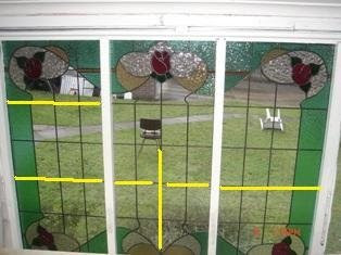
“These are the latest 3 panels I’ve made for my bungalow out the back. They measure 1100mm high by 500 wide approx. I’ve made them all with different reinforcement applications. I was told they would not need any but still wanted to strength them up.

“The middle you can see I broke the hinge line with two pieces of re-force and on the other two I’ve gone all the way through to the outer border. All other lead lines do not go more than 2 pieces of glass before they are crossed by another piece of lead to break up that hinge thing.

“Due to the size/design I’d appreciate your thoughts on what I’ve done being correct/overkill?”


The two outer panels are supported appropriately. I believe the right one is adequately reinforced, and the left is over reinforced, but there will be no harm. The middle one is not adequately reinforced. The broken horizontal reinforcement transfers the stresses to the middle. The vertical one also transfers the stresses to the middle, only a little higher.

For reinforcement to work, it needs to transfer the stresses to the sides/tops of the panel where they will be captured by the framing. Thus the reinforcement needs to be a continuous line. The strongest reinforcement will be across the shortest dimension of the opening.

The weaving of the lead lines described by you as “lead lines do not go more than 2 pieces of glass before they are crossed by another piece of lead to break up that hinge thing” is exactly the right thing to do in these panels.

In the case you are illustrating, there should be no problems for several generations at minimum and possibly for a century.


"I’ve also included one other piece I’ve designed and cut which is going to be installed in an internal wall inside a home. Its 800/800mm approx and due to it being kept out of the weather was wondering about what type of re-enforcement structure would suit?"


As this will be an internal panel, I suggest that the best reinforcement would be a toughened/tempered sheet of 4mm float glass installed behind the panel. This will provide support in case someone leans against it. Yes, there is a diagonal hinge at the trunk, but the strongest reinforcing for this would simply be a horizontal bar behind the panel, which would look ugly and I don't think you want anyway.