Showing posts with label Fused Glass Classes in Glasgow. Show all posts

Wednesday, 28 April 2021

Sharp points on rectangles


At the conclusion of firing pieces with right angles or sharper shapes you often find very sharp needle points at the corners.


This is a result of the expansion of the glass as it heats up.  At top temperature, the glass piece is larger on the shelf than when you put it in cold.  The amount of this expansion is related to the thickness of the piece and the temperature it has been fired at.

As the glass cools, it contracts.  The contraction at corners and points has greater effects on the glass than at the sides.  The corners are contracting from two sides rather than only one.  This makes them a little more resistant to contract and often leaves a little of the glass stuck at the furthermost point of expansion as it contracts.


I have found the best prevention of sharp points on the corners of rectangular pieces, and those with even sharper angles, is to nip off the tiniest bit of the corners. This very slight blunting of the corners allows the glass to expand and then retract without the corner or point catching on the separator and so creating the sharp needles.

Further information is available in the e-book: Low Temperature Kilnforming.


Wednesday, 17 February 2021

Recovering from Devitrification


An explanation of what devitrification is, can be found in the link.

Mild devitrification is generally a smeary appearance on the surface.  Most often this can be corrected by either removing the surface, adding a flux or putting another surface over the piece.

mild devitrification
photo credit: Bullseye Glass Co.

Removing the devitrified surface

Sandblasting and grinding are two common methods of removing the surface. If you have access to a sandblaster, this is the easiest method of removing the surface.  You can remove the surface with manual methods too.  You can use wet and dry sandpapers, starting with coarse ones and proceed through grades to at least 400grit (0.037mm).  The flexibility of the sandpapers is that they can conform to uneven surfaces that tack fusing provides, to remove devitrification in depressions as well as the high bits. Diamond hand pads and sheets do the job more quickly, but are more expensive.

Acid etching is another surface removal method. There are various etching creams on the market which will remove the surface. You need to apply and leave for a long time to allow the acid to work on the glass surface.  It is best to keep the acid paste damp to enable the acid to work over a long period.  A piece of cling film will work well.

Making a new surface

You can provide a new surface by using devitrification sprays.  There are both commercial products and do it yourself ones that work.  The do it yourself product is a borax solution.  The method for making the solution is given here.

Borax powder

You also can give the devitrified surface a new one by covering it with clear powders.  Powders sifted evenly over the surface until there is a thin covering over all the piece will give a new surface concealing or covering the devitrification.  Fine frit does not work so well, as more needs to be sifted over the surface.  This will not be applicable to tack fused pieces, as the whole piece needs to be taken to a contour or full fuse to make sure the powder or frit is completely smooth.  This will make the tack fused areas flat.

Left to right - devitrified surface, powder covering, fired piece
Photo credit: Bullseye Glass Co.

When dealing with devitrification, the whole of the surface should be treated, not just isolated areas.  Treating isolated areas will most probably leave a difference in appearance between the treated and untreated areas.  It is not worth the risk of having to fire yet again.


Dealing with devitrification usually involves removing the devitrified surface or making a new one.

Wednesday, 23 September 2020

Making Thin Sheets

The question of how to make thin sheets arises from time to time.  Unless you are a glass manufacturer, it is unlikely you can make large, thin glass sheets.  But you can approximate making thin sheets by two methods that I know.

Sintering

One of these is sintering.  This is firing the glass to a low temperature and soaking for a long time.  The common form of this is powder wafers. 

By using a screen to deposit an even layer of glass powder you can make very thin, but delicate sheets of glass.  The procedure I would use is a screen of about 45 – 60 threads per inch.  This is coarse enough to allow the powder through, but not so fine as to “reject” large amounts of the coarser particles. 

You can screen the powder directly onto a kiln washed shelf, or onto Thinfire or Papyros.  You will not be able to move the unfired powder on a sheet of paper or fibre paper without changing the thickness and shape of the screened powder.  It must be laid down onto the separator directly on the shelf.  You can of course, move the shelf to the kiln if you can get in without tipping it.


Method

Support the screen about 3mm above the surface to allow the powder to fall through.

Make a ridge of powder at one end of the screen.  Using a smooth straight edge wide enough to cover the whole of the screen, lightly spread the powder from the starting end to the other. Then repeat drawing the powder to the starting end.  Make about five repeats of this – that is 10 passes, to get enough powder laid down to form about 0.5 to 1mm sheet.  You will need to experiment with the number of passes to get what you want.

Do not try to press the powder through the screen.  That will only wear the screen out quickly and may tear it.  Each pass should be a light spreading of the powder.  It is heavy enough to fall through the screen without additional force.

You could, of course, just sift the powder over the area you want to cover and judge by eye how even the layer is.  It is possible that your observation is good enough, but it is more likely that you will have thick and thin areas.  Often even at sintering temperatures, the thin is pulled toward the thicker, leaving small or large holes.   By screening the powder, you know you will have an even layer


Firing

The kind of schedule to use to sinter the glass particles together without changing their structure is the following:
220°C to 482°C , soak for 60 mins
55°C to 593°C, 10 minutes
28°C to 665°C for 5 mins
as fast as possible to 482°C for 30 mins
28°C to 427°C, no soak
55°C to 370°C, no soak
110°C to 50°C, no soak
This will work for most fusing glasses.

This slow firing allows enough heat to penetrate the glass grains that they will stick together without changing shape or developing holes.  I admit the anneal cool is very cautious.  You can experiment with quicker cools if you want to speed the process.

  
Pressing

This is a technique of thinning already existing sheets of glass.  Typically, you will have a 6mm or thicker piece of glass that you want to be 3mm or less.  Paul Tarlow has described this kiln pressed glass very well in his books and on the fusedglass.org site.

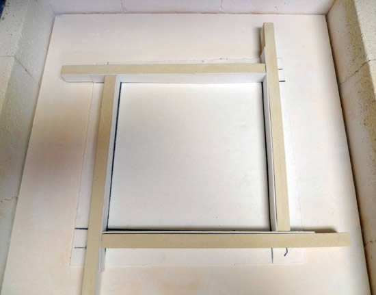
In essence, you use a pair of kiln shelves.  Kiln wash both shelves.  Place the glass to be thinned on one shelf.  At the outer edges of the shelf put down spacers of the thickness you want the glass to be after pressing.  This will keep the upper shelf from settling down too much and more importantly unevenly.  Place the other shelf, kiln washed side down, on top of the glass.  Be sure the spacers are in places where they can support the upper shelf.


If you are thinning from 6mm to 3mm, normally you do not need any additional weight on top of the upper shelf.  But the thinner you want the glass to be, the greater the weight needs to be.  It could be another shelf, fire bricks or steel weights.

When scheduling the annealing remember you must take account of the mass of the weight on top of the glass.  You will need a much longer temperature equalisation soak and a much slower annealing cool.  

Further information is available in the ebook Low Temperature Kiln Forming.

Wednesday, 20 November 2019

Pot Melt Contamination

Pot melting occurs at temperatures above that for which kiln washes are designed. This means the kiln wash most often sticks to the back of the melt.

If you put only fiber paper – Thinfire, Papyros, or standard 1mm or 2mm fibre paper – at the bottom, the dripping glass will tear and move it about.  It also tends to incorporate fibers from the refractory papers into the melt.  It is best to avoid fibre papers of any kind on the base.  Using fibre paper around the edges of dams, if you use them, is better than simple kiln washing of the dams.

From wikihow


If you have a sandblaster, it is easy to take the kiln wash off leaving a matt surface. You can live with this for many purposes, but if you want a more polished surface you can take the melt up to fire polishing temperature to shine up the surface. You will need to flip this over and fire again, if the original top surface is what you want to present.  Or if you like the new shiny surface, use it as is.

If you are going to cut the pot melt up for other uses, there is no need to fire polish as the surface does not matter, only the cleanliness, and removal of contaminants.


There is another thing you can do to avoid kiln wash contamination.


The best solution appears to be to put a disk or rectangle of glass on top of fibre paper. It can be clear or any colour you wish, but needs to fill the area enclosed by the dams. This seems to keep the fiber paper from tearing and being incorporated into the glass, even though the base will have the fibre paper marks.


It also works very well when you are confining the melt to get a thicker disk. Make sure you have kiln washed the sides of the container or dam very well, in addition to 3mm fibre paper arranged so that it is 3mm narrower than the expected final thickness, or any excess glass may stick to the dams. The means of arranging the fibre paper around the dams is given here. You may need to grind the marks off the edge of the disk, but this is much easier than grinding it off the bottom.

Saturday, 2 November 2019

Schedules for Steep Drapes

I have been asked for a schedule for draping in the context of a tip on steep straight sided drapes.

What you are trying to do with a steep drape is two things. One is to compensate for the heat sink that the glass is supported by, and the second is to compensate for the relative lack of weight at the outer edge of the glass.


The supported glass transmits its heat to the support, leaving it colder than the unsupported glass. This often leads to breakage due to heat shock at much lower temperatures and slower rates of increase than glass supported at its edges. My experience has shown that - contrary to what I recommend for other kinds of firings - a slow rise with short soaks at intervals up to the working temperature works best. The reason for these slow rises and soaks is to try to get the support and the glass to be as nearly as possible at the same temperature throughout the rise in temperature. The soaks help ensure the mould is gaining heat without taking it from the glass.


The other problem with steep drapes is that the edges of the glass begin to drop more quickly than the area between the support and the edge. This leads to the development of an arc that touches the mould side near the bottom before the glass between the edge and the and the support. Extended soak times are required to allow the glass to stretch out and flatten. If this is done at high temperatures, the glass will thin - possibly to the extent of separating.


So the requirements for a firing schedule on this kind of drape are slow increases in temperature with soaks to avoid thermal shock, and an extended soak at the (low) forming temperature.


Whether using steel or ceramic moulds, I use a slow rise in temperature to 100C with a soak of 15 minutes. I then increase the rate of rise by 50% for the next 100C and give a 15 minute soak there. For the next 200C I raise the temperature at twice the original temperature rise, again with a 15 minute soak. The glass and mould should now be at 400C. This is still at the point where the glass could be heat shocked, so I only increase to 2.5 times the original rise rate but use this rate all the way to forming temperature.


Each kiln has its own characteristics, so giving schedules is problematic. 


  •  A side fired kiln will need slower heat rises than a top fired one. 
  • The closer the glass is to the elements, the slower the rate of increase needs to be. 
  • The kind of energy input - electric or gas - has an effect. 
  • The thickness of the glass is also a factor in considering what rate to use. 
  •  The size of the glass in relation to the size of the support is important - the greater the differential, the slower the heat rise should be. 


So in making a suggestion on heat rises, it is only a starting point to think about what you are doing and why you are doing in this way.

I have usually done this kind of draping in top fired electric kilns where the elements are about 250mm above the shelf, and about 120mm apart. In the case of a 6mm thick piece about three times the size of the support area, I use 50C/hr as my starting point. This is one third of my usual rate of temperature rise. However you must watch to see what is happening, so that you can make adjustments. You should observe at each of the soaks, so you know how the glass is behaving. It will also help you to pinpoint the temperature range or rate of advance that may be leading to any breakages.


On steep slumps, the temptation is to use a high temperature to complete the drape. This is a mistake as the glass will be more heavily marked and tends toward excessive stretching and thinning. What you really need is a slow rate of advance to a relatively low temperature. If you normally slump at about 677C, then you want to do this steep, straight sided drape at 630C or less. It will need a long soak - maybe up to an hour. It will also need frequent observation to determine how the drape is progressing. So plan the time to make yourself available during this forming soak.


Annealing is done as normal, since the mould and glass are more closely together and will cool at the same rate.


The original tip on the set up of a steep straight sided slump is here.

Tuesday, 29 October 2019

Damming Ovals

There are various ways of damming oval shapes in kiln forming. Some of these are outlined here.

One set of methods depends on having a soft surface such as ceramic Fibre board or vermiculite.

Photo from Clearwater Studio


You can wrap your shape with fibre paper. For this you need to cut a strip or strips 3mm narrower than the height of the piece you are wrapping. You then stick sewing pins down through the fibre paper and into the shelf of fibre board or vermiculite. This will be easiest if you use 1 to 3mm thick fibre paper, as the pins must not contact the glass – the pins will stick to the glass if they do.


You can cut a form out of ceramic fibre board and use that as a dam. You can pin this to the base fibre board or allow it to merely rest on the board. It is possible to cut arcs from fibre board and place them around in sections. In this case they will need to be pinned together so they do not move apart. Staples can form the attachments. You can make your own – larger – ones from copper wire.

You can buy stainless steel banding which needs to be lined with any separator – batt wash or fibre paper.

Bonny Doon stainless steel dams


You also can layer fibre paper up to the height required – remember 3mm less than the thickness of the piece. You then need to fasten the layers together to avoid movement between the layers.


If you are firing on ceramic kiln shelves the same materials can be used but need to be supported a little differently.

If you are wrapping the piece on mullite shelves, use some pieces of kiln furniture to block the strips up against the glass. The thicker the glass, the more weight will be pushing out against the dams and the sturdier the dams will need to be. Make sure the strips contact the shelf evenly- if you have gaps, you'll have leaks.

The disadvantage to this method is that the glass can take up the irregularities of the kiln furniture.

You can use fibre board with a void cut out to the shape required and place it on the shelf.


You can also use layers of fiber paper around the shape and pin the layers to each other. This is the same method as used on ceramic fibre board.

Again stainless steel can be used to form the dam. Remember to line the steel with fibre paper that is 3mm narrower than the height of the piece.


In all these cases of dammed forms, the edges will be of varying degrees of roughness and some cold working will be required.

Saturday, 22 June 2019

Slumping unknown glasses

I had a recent request for help from an old friend who has taken up kiln formed glass. The problem is common enough, that (with her permission) I am adding it to the tips section.

I tried an experiment today to use some of my nice (non-fusing) glass. I cut at 270 mm diameter circle from a 3mm thick sheet and wanted to slump it into my 270 mm bowl mold. I set the mold up carefully and checked it was dead level in all directions and that the glass was absolutely centered on it. I have no idea what the COE is so decided just to use the S96 recommended slumping temperature of 650C. When I checked the kiln no more than 2 minutes after it had reached 665C, the glass had slumped almost to the bottom of the mold but it had slumped very asymmetrically. There was also a small burp on one side which has never been an issue when slumping bowls in this mold before.

The schedule I used was as follows:
200C/hour to 540C, 0 hold
650C/hour to 665C, 10 hold
Then standard S96 anneal programme

Also, the edges were still a bit rough from the cutting, i.e., they hadn‘t fire polished at all. Can you help?


Finding out about the softening characteristics of the glass

Slumping a single layer of glass with unknown characteristics – the CoE is not really relevant – requires that you watch it and other similar ones until you have established a slump temperature for the glass.


There is a way to do it:
Cut a piece of glass 305mm long by 20mm wide. Support it 25mm above the kiln shelf with the posts being 290mm apart. Put kiln furniture on top of the glass where it is supported. Make sure you can see the shelf just under the middle of the suspended glass when you are setting up this test. You can put a piece of wire or other dark element there on the floor of the kiln to help you see when the glass touches down.

Set the kiln to fire at 100C/hour to about 680C. Peek at the suspended glass every 5-10 minutes after 560C to see when the glass begins to move. Then watch more frequently. If your kiln has an alert mode on it, you could set it to ring at each 5C increase in temperature, otherwise use an alarm that has a snooze function to make sure you keep looking. When the glass touches down to the witness sitting on the shelf, record the temperature. This will approximate the slumping temperature in a simple ball curve mould.


Getting smooth edges

You need to have smooth edges before slumping. You can fire polish the piece of glass to get rounded edges, or you can cold work the edges with diamond hand pads, working from the roughest to the finest you have available. If that does not give you the edge you want, you will need to fire polish before you try to slump.

You can do at least two things to find the fire polish temperature. You can do a little experiment by using the cut off pieces of the glass and roughing them up a little before putting in the kiln. Make sure you can see it through the peep hole(s). Set the kiln to fire at about 250C to say 750C. Look in from about 700C to determine when the edges begin to round.

The other is to put a strip of the same glass in with the slump test and set the kiln to go up to 750C rather than just 680C. You can check on progress just as for the separate firing to determine the fire polish temperature. I think about 40C above slump temperature should be enough, but your test will determine that.


Avoiding uneven slumps

Most uneven slumps occur because of too fast a rate of increase in temperature. The piece can hang up on the mould sometimes causing the glass elsewhere to slide down to compensate. The real difficulty in the schedule was the 650C/hour rate up to the top temperature. This was so fast that the glass at the edges would have the opportunity to soften and so hang before the centre was soft enough to begin to bend. 150C / hour would be fast enough from 540C to achieve the slump.  In fact, 150C/hour all the way to the slumping temperature would be fast enough.  The glass reacts well to a steady input of heat rather than rapid rises, even with soaks at intervals on the way up.

Other things can be done too. You mentioned the edges were rough from the cutting. This can cause difficulties of hanging. To avoid that, you should smooth the edges before placing the glass on the mould. A further precaution against uneven slumping is to give a slight bevel to the bottom edge so that it can slip more easily along the mould.

You had already done the leveling of the mould and the centralization of the glass on the mould. These are two other things that can cause uneven slumps.


Avoiding “burps”

The glass slipping a long way down the mould is often accompanied with burps or bubble like up-wellings. These are both indications of too high a temperature being used to slump. I would begin looking at the glass from about 600C in the slumping of any unknown piece of glass. That would apply to any new configuration of the glass or mould too. The fact that the glass slid to the bottom and had a burp means that the temperature was too high and too fast. Once you have established the lowest slumping temperature, by watching to see when it begins, you then can add about 30 minutes soak to that temperature. The length of this soak will have to be determined by observation and experience, though.

A slow heating allows the glass to be at an even temperature throughout its thickness. A rapid rise with a thick piece will sometimes reveal a tear like opening on the underside of the glass that does not come through to the top. This is because the upper surface is sufficiently hot to begin slumping while the bottom is just a little too cool. If there is too great a difference, the glass just breaks all the way through.

Also slow heating allows the slump to be accomplished at a lower temperature, leading to fewer problems and to less texture being taken up from the mould.


More detailed information is available in the e-book: Low Temperature Kilnforming.

Tuesday, 22 May 2012

Stress Testing

You should be testing for stress in any new set up. This includes new processes, different layering, different colour combinations, and any other variation that you make in your basic processes.

You can buy kits called stressometers. The devices called stressometer are not actually meters. They are battery powered light sources with two pieces of polarized film in frames. This is very good for small kiln formed pieces. For larger pieces you can use your light table with larger pieces of polarized film. A description of how to use these is given here.

Stress appears as a “halo” of light around the stressed areas. The more light that appears in, or at the edges of the piece, the greater stress is being indicated. The amount of acceptable stress is given in a Bullseye Technical Note.

However, if you test only the combination of glass you propose to use, you will not know if the stress is from incompatibility or from annealing – the appearance is the same for both. This means that you need to place an additional test into the kiln, to determine the adequacy of annealing. This is especially important when tack fusing and doing thick work. The process for doing this is given here.

Wednesday, 4 April 2012

How Annealing Affects Slumping


It is often claimed that inadequate annealing of the fused blank can cause breaks during a slump firing.

If annealing is the cause, it is likely to break on the rise in temperature.  Once the piece has reached the annealing temperature, any breaks will be due to thermal shock on the way down.  An annealing break usually has a hook at both ends of the break, although this is more difficult to determine in a shaped piece.

Thermal shock tends to be along straight(ish) lines, often between thick and thin, or strongly contracting colours.  It tends to happen on the cool down. 

Breaks on the rise or fall in temperature are difficult to distinguish on slumps.  The temperature is low enough that there is little to distinguish the sharpness of the edges.  The real method of determining, is to try to fit the pieces together.  If they fit exactly, the break was during the cooling.  If they have even a little variation in fit, the break occurred on the rise in temperature.

If the annealing of the slump is marginally inadequate, it may break hours, days, weeks after cool.  The less stress the longer it will survive.  This will not be the result of any inadequate annealing of the fused blank. Only the last annealing is relevant to the soundness of the piece.

How can you ensure the annealing on a slumped piece is adequate?

You need to check the fused blank for stress before slumping to ensure it has no or very little stress.  The anneal for unstressed items needs to be at least equivalent to, or longer, as for the fused blank.  Testing has shown that annealing for one layer greater than the calculated thickness results is less stress than annealing for the thickest part.

Fire more slowly than usual for blanks with moderate stress to avoid thermal shock during the first ramp.  Anneal the slumped piece for one layer more than was done for the blank.  There is no other requirement for slower annealing.

Pieces with significant stress need to be returned to the kiln to be annealed.  Fire them up significantly more slowly than you normally would for a piece that thick.  This may be one half or less the speed used on the un-fused pieces. Anneal as for a thicker piece.


Wednesday, 24 November 2010

Designing a Pattern Bar

Assuming that you are not going to just dump your scrap glass in a random pattern to form a pattern bar, you need to spend some time designing it.

The simplest kind of bar is composed of strips of glass which are stacked or assembled in the kiln, but there are many other more elaborate configurations.

Because of the additional annealing time required for larger and thicker items, most pattern bars range from 1" by 1" to no larger than 2" by 2". The length of the pattern bar can be any length, up to the maximum that will fit in your kiln.

The design process begins by thinking about the cross section of the bar. This is what will appear when cut and assembled. As a simple exercise, assume you are making a diamond pattern in the bar. You can draw this out using 3mm as the thickness (or 1.5mm if you are using thin glass). Rough out the pattern and then begin using 3mm as the grid. Remember that you will need to cut your strips 4mm or wider to obtain a clean break. As you plan it out you will see that you need one length at the base one half of the space remaining after you have laid down the first, central piece for the diamond. The next layer will have two strips for the diamond, giving a requirement for one strip to fill the space between the two for the diamond shape and two strips each one half the remaining space. This process goes on until the area is filled.

Saturday, 20 November 2010

Pattern Bars

A pattern bar is a thick bundle of glass that has been fused together. These can be in the shape of a rectangle, or can be a thick pot melt – whether a disc or a rectangle. The length of the individual bars can be as long as your kiln allows, but needs to be practical to handle when cutting.


The basic steps involved in making a pattern bar include deciding on a design –whether controlled or random, cutting glass for the bar, assembling the cut glass into the desired bar shape, then firing to a full fuse. Once fired, pattern bars can be cut into slices with a saw - tile, glass, lapidary, or stone – which uses water for cooling and lubrication. The individual slices are then assembled and re-fused to make bowls, platters, and similar shapes. They can also be used as accents in any number of applications.

There is a caution about using pattern bar pieces. As the glass in the bars has been fired to a relatively high temperature, some of the characteristics may have changed. So you need to do a compatibility test before doing the main piece.

Designing Pattern Bars
Boxes for Pattern Bars
Dams for Pattern Bars

Sunday, 12 September 2010

Lining Dams

Dams should normally be lined with Thinfire and fibre paper to get the best release. If you are using fibre board that has not been hardened, you do not have to line, but you will get smoother edges if you do.

As described by Helios


The lining papers should be about 3mm shorter than the expected final thickness of the finished panel. I find that 3mm paper against the dam provides the required standoff between the dam material and the glass. The lining of the fibre paper with Thinfire provides a smoother surface than just the fibre paper. Both of these liners should be the same height – 3mm less than the final height of the finished piece.

To calculate the expected final height you need to do a few calculations in the metric system.  Weigh the glass in grams.  Divide by specific gravity (2.5) to get the number of cubic centimeters.  Divide the cc by the area enclosed by the dams in square centimeters. This will give the fraction or multiple of centimeters thick the glass is predicted to be.  

Example:
The weight of glass = 500 gms
The specific gravity = 2.5
The area is 10cm by 10 cm = 100 square cm.

Divide 500gms (the weight) by 2.5 (the specific gravity) = 200 cubic centimeters.  Divide 200 (the volume in cc) by 100 (the area) = 2 cm thick final piece for the amount of glass put into the pot.

This indicates the fibre paper should be 1.7cm high to allow enough space for the bullnose edge to form.


Saturday, 10 April 2010

Charging the Pot for a Melt

The way you charge (load the glass into) the pot makes a difference to the resulting piece.

A good way to get strong colour separation is to put two colours on opposite sides and a third colour or clear between them. The two side colours will have best separation if they are not more than 1/3 each. As the glass begins to flow out of the pot, all three colours will come out at once and form concentric circles (assuming a circular hole in the pot).

Vertical stacking of multiple colours


You can manipulate and alter the results with a fair amount of predictability by changing the diameter and shape of the hole, charging the pot with more than three colours or less, rearranging the orientation into a sunburst orientation or whatever comes to mind. Be sure to keep notes on what you did and what the results were in case you want to reproduce the effect.

Think about how the glass will flow out of the pot when you charge it with glass. If you layer colours horizontally from C (on top) to A (on bottom), it will initially flow out in colour A, then B, then C. After that initial flow, which will be on the outside of the finished piece, the main flow will be from the top (C), then the middle (B) and finally the bottom (A). This is because after the initial flow, the rest of the glass comes out in a funnel shape pulling the top and small portions of the underlying glass.

This means that layering is the best way of mixing colours. You need to think about colour combinations too. For example yellow and red become brown; yellow and blue a dark green, etc.

The proportion of dark colours is important, for example, as little as 2% of black can make the whole piece very dark. If you have dark colours, you need to add a large proportion of clear or very light opalescent glass.

If you use frit, large pieces are better than smaller ones. Even so, you need to be careful about the colours you use so the whole does not become muddy.

Tuesday, 6 April 2010

Aperture Pours

The most commonly used aperture pours are Pot melts and wire melts. Pot melts use containers, and wire mesh for wire melts. In both cases they control the way the glass melts into a container or directly on the shelf below.

Emptied pot melt

The materials are stainless steel wire grids, and unglazed terracotta pots. The spacing of the steel grid will determine the number of trails of glass falling. So a finer grid will give more points of expansion in the resulting melt. But will mix the colours much more thoroughly than a coarser mesh will.

Finished screen melt


Doing a pot melt usually provides a simpler pattern of flow. A single round hole gives one circular point from which the glass expands. A single rectangular hole gives a single ribbon shape as the expansion point. You can, of course, have multiple holes in the bottom of the pot to provide a more complex interaction of the flowing glass. The wider the rim of the pot in relation to its depth, the more flexible it will be. You can put more glass in the pot and you can have it higher in the kiln.

The arrangement of glass in the pot will produce different results. There are two basic arrangements: colours layered one above each other as in a layer cake; and colours arranged on end around the sides of the pot. When loading the pot you need to remember that although the glass immediately above the hole will be the first to come out – and therefore be at the edge of the melt – the remainder of the glass comes out in a funnel-like order, with the glass at the bottom corner of the pot being the last to flow out – and become the centre of the melt.

There is a relationship between the hole size and distance to surface that affects the final appearance. The larger the hole the less likely the glass is to spiral as it falls, so you need a greater distance between the bottom of the pot and the shelf. The smaller the hole, the less distance you need. Only experience will tell you what distance and size you need or can use.

You can calculate the amount of glass for different sizes by using this table. If you have a rectangular space you are dropping into, you can calculate the volume of glass by multiplying the width, length and desired thickness – all in centimetres. This will give the volume in cubic centimetres and to convert that into weight, you multiply the volume by the specific gravity of glass - 2.5 is near enough – to get the number of grams of glass required. To convert into kilograms, divide by 1000.

By dropping directly onto kiln washed shelf, ring or circular container you will get some contamination.  There are some ways to avoid this given here.

You can also use this method to act as a crucible to pour glass into closed moulds.

Saturday, 6 March 2010

Commissioning

Commissioning a stained glass window, screen or lamp involves entering into a contract with the designer/maker. It is therefore important that both client and maker know exactly what is involved.

· The price of the work should be established. The materials used in the making of a window, especially the glass itself, can be expensive and the possibility of commissioning a well-designed leaded light should not be ignored.


· The maker will need to know the budget for the work and will provide an estimate, and may require a down payment before beginning work and perhaps payment by instalments, depending upon the cost of the materials involved.


The designer will prepare a preliminary design, according to the client's brief.


· The design should indicate the nature of the construction and the position of any ferramenta or physical support.


· This design should be as detailed as possible. It may be accompanied by samples of the proposed glasses.


· The client must be prepared to recompense an artist for design(s) prepared according to a brief, whether or not it proceeds to execution.


· The copyright in all cases remains the property of the artist.


The arrangements for the execution of the commission must also be satisfactorily established, including those for installation. If necessary, the advice of an architect should be sought; for church commissions, the architect responsible for the church should be involved from the outset. If the window is to be sited in an exposed position or in an area where vandalism is known to be a problem, protective measures should be considered.


Also look at Commission Agreements

Tuesday, 2 March 2010

Effect of Plaster-Water Ratio on Some Properties

Plaster-water ratio (by weight) 100/30

Setting time (min) 1.75

Compression strength (kg/sq.cm) 808
Dry Density (kg/cu metre) 1806

Plaster-water ratio (by weight) 100/40

Setting time (min) 3.25

Compression strength (kg/sq.cm)474
Dry Density (kg/cu metre) 1548

Plaster-water ratio (by weight) 100/50

Setting time (min) 5.25
Compression strength (kg/sq.cm)316
Dry Density (kg/cu metre) 1352

Plaster-water ratio (by weight) 100/60

Setting time (min) 7.24

Compression strength (kg/sq.cm)228
Dry Density (kg/cu metre) 1206

Plaster-water ratio (by weight) 100/70

Setting time (min) 8.25

Compression strength (kg/sq.cm)175
Dry Density (kg/cu metre) 1083

Plaster-water ratio (by weight) 100/80

Setting time (min) 10.50
Compression strength (kg/sq.cm)126
Dry Density (kg/cu metre) 990

Plaster-water ratio (by weight) 100/90

Setting time (min) 12.00
Compression strength (kg/sq.cm)98
Dry Density (kg/cu metre) 908

Plaster-water ratio (by weight) 100/100

Setting time (min) 13.75

Compression strength (kg/sq.cm) 70
Dry Density (kg/cu metre) 867


This table of relationships makes it clear that the less weight of water added to the plaster, the stronger the resulting mould will be. It also is clear that with less water, the setting time is reduced. So some compromise may be needed to be able to pour the mixture before it sets.

Saturday, 27 February 2010

Properties of typical gypsum plasters and cements

Number 1 Pottery Plaster
% of water to dry mix by weight - 70%
Set Time – 27 – 37 mins
Dry density – 1105 kg/cubic metre
Expansion on setting – 0.21%
Compressive strength - 126 kg./square centimeter

No. 1 Casting plaster% of water to dry mix by weight - 70%
Set Time – 27 – 37 mins
Dry density – 1058 kg/cubic metre
Expansion on setting – 0.2%
Compressive strength - 140 kg./square centimeter

Plaster of Paris% of water to dry mix by weight - 70%
Set Time – 27 – 37 mins
Dry density – 1105 kg/cubic metre
Expansion on setting – 0.2%
Compressive strength - 140 kg./square centimeter

Number 1 Casting Plaster% of water to dry mix by weight - 65%
Set Time – 27 – 37 mins
Dry density – 1162 kg/cubic metre
Expansion on setting – 0.22%
Compressive strength - 168 kg./square centimeter

Pottery Plaster
% of water to dry mix by weight - 74%
Set Time – 27 – 37 mins
Dry density – 1162 kg/cubic metre
Expansion on setting – 0.19%
Compressive strength - 126 kg./square centimeter

Hydrocal Cement
% of water to dry mix by weight - 45%
Set Time – 25 – 35 mins
Dry density – 1442 kg/cubic metre
Expansion on setting – 0.39%
Compressive strength – 35 kg./square centimeter

Hydroperm Cement% of water to dry mix by weight - 10%
Set Time – 12 -19 mins
Dry density – 
<641 br="" cubic="" kg="" metre="">Expansion on setting – 0.14%
Compressive strength – 35 kg./square centimeter

Hydro-Stone cement
% of water to dry mix by weight - 32%
Set Time – 17 -20 mins
Dry density – 1913 kg/cubic metre
Expansion on setting – 0.24%
Compressive strength – 703 kg./square centimeter

Ultracal cement
% of water to dry mix by weight - 38%
Set Time – 25 - 35 mins
Dry density – 1568 kg/cubic metre
Expansion on setting – 0.08%
Compressive strength – 421 kg./square centimete
r

Tuesday, 23 February 2010

Break Down Temperatures of Common Mould Constituents

Binders are essential parts of mould materials. They hold the refractory parts of the mould together. Selection is dependent on the temperature you will be using. This also is important in choosing the refractory material to use.

Gypsum plaster - 704C – 816C
Hydrocal cement - 704C – 816C
Hydroperm cement – 760C – 927C

Colloidal silica – 1260C
Colloidal alumina – 1260C
Calcium alumina cement (cement fondu) – 1538C

There are of course, many other factors to take into account when choosing binders and refractory materials for moulds.