Wednesday 3 July 2024

Multiple Layers of Kiln Wash and Fibre

Recently, there have been confirmations of multiple of layers of kiln wash on the shelf under pot melts, frit stretches, and flows.  Ten, and even sixteen layers are mentioned. Also reported are two layers of 1mm fibre paper as a separator for the same processes.

These practices are excessive and wasteful.


Kiln wash   

·         Once fully covered, the shelf does not need additional layers. 

·         Stir the kiln wash mix each time you dip the brush.

·         Apply thinly.

·         Use only enough coats to evenly cover the shelf.


Fibre and shelf papers are not recommended to be placed on the shelf for high temperature processes.

·         The shelf papers can become incorporated within the glass as it moves along the shelf.

·         Fibre papers inhibit the movement of the glass in unpredictable ways.


If you do use fibre papers anyway:

·         Use only one layer.

·         Place a clear sheet of glass over the fibre paper to allow better flow during the firing.

·         A disc of clear glass also helps to separate opalescent glass from the shelf.


More layers of kiln wash or fibre paper does not make a better separator.


Wednesday 26 June 2024

Replacement Kiln Vent Plugs


Replacement Kiln Vent Plugs

Accidents happen.  Sometimes the lightweight plug for the vent of a kiln gets dropped and broken.  You can replace this, whether brick or ceramic.

A quick solution is to roll up some fibre blanket or thick fibre paper into a roll large enough to fit into the hole.  This is enough to keep the heat from escaping and stop outside air flowing in.  If you leave excess outside the plug hole, it allows you to pull it out and view the interior as usual.  This will last quite a while and can be renewed easily.

A more permanent solution is to shape soft fire brick.  This can be shaped with a cheap saw. The brick is soft but very abrasive. So, use a cheap saw or an old one.  I keep an old saw especially for shaping bricks and vermiculite.  You could use 50mm/2 inch vermiculite in this way too, but firebrick this thick or more is easy to obtain.

Cut a cube from a fire brick.  This usually is about one third of a full brick.


Mark all around with a pencil how thick the shoulder (the outer part of the plug) should be. 25mm or 1 inch is thick enough.  It is possible to have it thicker if you wish.  The important element is that the outside part of the plug should not over balance the neck that fits into the vent channel.

Present the brick to the vent hole and twist a little, this will leave a mark to determine the diameter required. Alternatively, measure the inside diameter and draw this onto the end of the brick with a soft pencil or charcoal.

One end of brick cube marked, although a little off centre

Saw down to the shoulder mark on each of the four corners. Then make it eight corners. Test how well this adjustment fits to the hole.  It is probable that it is too big on the corners, but ok on the flat sides.

The first four corners sawn off to the shoulder


This is the time to use a wood rasp to round the multiple corners. Repeat the testing for size and adjusting until the plug fits the hole.  


The plug should not be tight.  It needs only a loose fitting so that it is easy to remove and put in.

Fit too tight to slide easily into the vent.

Finally, with 60 grit sandpaper round off any remaining corners.  Test and sand more off until it slides easily into the hole. This should not take more than a quarter of an hour to complete.


Fit just right. It slides in and out easily.


Wednesday 19 June 2024

Slumping Breaks on “go-to” Schedules

 An "It has always worked for me before" schedule implies a single approach to slumping regardless of differing conditions.  Layup alterations, thickness variations, colour contrasts, mould variations all affect the scheduling.  The schedule for each piece needs to be altered when there are changes from the schedule for the “standard” piece, or mould.

Photo credit: Emma Lee


In the example shown, we are not told the schedule, but it shows that the rate was a little too fast. If it had been faster the glass would have separated further apart. The heat was enough to appear to recombine at the edges where it was not slumping so much. 

Review your "go to" schedules whenever something changes. It may still be a good base from which to work. But you need to assess the layup, thickness, and any other variations to help adjust the schedule to fire each piece.

Some of the variations from the “standard” to be considered are:

Single layer slumping 

Weight

Mould sizes

Relative Slumping Depth

Mould shape and detail


Wednesday 12 June 2024

How Many Times Can You Fuse?

Is there a limit to how often a piece can be refused either to add on new pieces or to break up and reuse?


Bullseye test their glass to ensure it can go through three firings.  After that you are on your own.  This limitation has been generally accepted within the kilnforming community.

Multiple Firings

Many people report that they fire their glass many times.  I have fired Bullseye glass up to seven times using powders.  The first five firings were to contour fuse.  The final fuse firing was to full fuse.  And then there was a slump firing to make up the seven firings.  These multiple firings assume that the temperature is not taken above full fuse for any of the firings.  The annealing for each of these firings remains as for the calculated thickness of the piece.  No additional annealing time is required for multiple firings without significant changes.

You do not need to consider firing multiple process at once.  The possible number of firings is more than enough to achieve multiple processes.

High Temperature Work

However, the many firings of my piece would not have been possible with high temperatures or long soaks.  The high temperature firings are those that go to casting temperatures (835ºC/1540ºF) and above. These are temperatures for things like pattern bars, melts, and castings.  The glass can change its nature enough to give problems at these temperatures, especially with long soaks.  

If you do multiple firings at high temperatures, I recommend annealing to be from one and a half to two times the expected thickness.  And the rate of cooling will need to be in line with the length of the anneal soak.

Even with care, there can be problems.  I created a thick bowl from transparent glass, of which I was proud.  After an afternoon in the sun while on display months later it showed a crack developing.  I am still convinced - by other similar work surviving – that I annealed it properly. It exhibited minimum stress after the final flat full fuse firing. It was not checked after the slump.

Multiple firings of items with soaks at high temperatures are less likely to survive.  The number of firings possible can be determined only by experience.

Wednesday 5 June 2024

Diagnosing Slump fractures

Once you have an initial idea of the source of the problem, think about it.  Test it against the evidence.  Is there enough evidence to make a call?  Make sure you have considered alternative explanations.  It is just too easy to make a snap decision about causes in low temperature processes.  The source of breaks in slumping are most often complex and stem from interrelated factors.

I give you an example of the difficulties of diagnosing a slumping break.

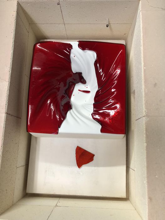
On a Facebook group a person showed the break of a single layer on a cyclone mould.  Others commented the same had happened to them.


Picture credit: Esther Mulvihill Pickens

Possible causes suggested on Facebook included:

  • Thermal shock on the way up
  • Thermal shock on the way down
  • Too large on the mould and broke due to differential contraction
  • Too many holds on the way up
  • Too hot
  • Too thin
  • Follow the CPI programme
  • Glass extending over the sides

Some of these suggestions were of general applicability, some in relation to the state of the broken glass.

The suggestions did not include:

  • Cause of the rounded dots at the bottom of the mould.
  • A cause for the state of the flat piece off the mould (it appears sharp edged.  Does it show some forming already?).
  • The cause for the location of the fully formed remaining glass.
  • The effect of the location of the mould and glass in the kiln.
  • The consequences of a short soak at top temperature. 
  • Is the kiln running hotter than most (1290ºF/698ºC for 10 minutes at top temperature was used)?

Of course, it is difficult to diagnose a problem from just one picture. It is difficult even with many pictures. And so, without handling the object, only suggestions can be made.

But….

You must spend enough time examining the piece with whatever other information is available to make specific suggestions.  The first thought may not consider all the factors.  Consider what kinds of causes there are for breaks during or after slumping.

More close inspection reveals the rounded edges of the break.  That supports the idea that the temperature was too high. It also supports the diagnosis that the break occurred on the heat up.

The edges of the piece that has fallen off the mould, and now rests on the shelf, seem to be square or sharp. This shows the extent of the difference of temperature between shelf and top of the mould – less than 100mm/4 inches.  Also, how small the differences in temperature are between slump and tack.  The extent of difference in fusing does depend on how high in the kiln the mould is placed.  That is demonstrated here by the different elevation of the two pieces. 

The conformation of the glass to the mould is complete.  This supports the diagnosis of the break occurring early in the firing, and certainly before the slump was complete.  These pieces will not fit together.  So, even if the edges were sharp the fact they will not fit together shows they conformed independently to the mould surface.  Therefore, the break was before forming temperature was reached.

The glass hangs over the mould edges on only three sides and at an angle.  This indicates the cause of the overhang was the break.  Not the reverse. An overhang at the beginning of the slump is likely to be even.

The piece on the floor of the kiln combined with the movement of the glass toward the back gives an indication that the origin of the break is at the front.  This relates to uneven temperatures and to the placement of the mould.

No one mentioned the placement of the mould and glass at the back of the kiln.  This will have an effect on scheduling.  The mould and glass are very large in relation to the kiln.  There is little space between the glass on the mould and the walls of the kiln.  Also, the mould is placed asymmetrically in the kiln – very close on three sides.  This will cause uneven heating in any kiln.  To have a successful firing of glass on this mould in this kiln will require radically different schedules to that for a centrally placed mould that is moderate for the size of the kiln.

The large size (relative to the kiln) and the asymmetrical placing are the causes of the break, in my opinion.  I admit that it took me several looks to realise the placement was a key cause of the break.

So, the generalised comments about thermal shock are correct, but not as to the cause of that shock.  The kiln will be hotter in the central part and cooler at the corners.  This is true of all rectangular kilns.  The important thing is to learn how to cope with these temperature differences.

Slow firings to low temperatures with long soaks are the three important elements.  These make up the heat work of the kiln. Applying this to a schedule means:

  • slow ramp up rates – as little as one half the recommended rates for centrally placed moulds that are moderately sized in relation to the kiln.
  • Low temperatures present lesser risks to the control of the outcome of the firing.  Determining the lower temperature possible requires peeking into the kiln to monitor the progress of the firing.
  • Long soaks combined with low temperatures get the kilnforming done with minimal marking of the underside.  Low temperature soaks - in excess of 30 minutes - are required to minimise the marking.  Observation of the slump will be necessary to determine when it is complete.

My suggestions for the causes of other elements are:

·        Cause of the rounded dots at the bottom of the mould.

The temperature was too high. 698ºC/1290ºF is much hotter than needed for a slump. It was hot enough to round edges and small shards of glass.  Which shows excessive heat was received by the glass.

·        A cause for the state of the flat piece off the mould (it appears sharp edged. Does it show some forming already?)

The soak of 10 minutes was too short for the temperature in the kiln to equalise from top to bottom.  The glass on the shelf may not have reached 650ºC/1200ºF with such a short soak.

·        The cause for the location of the fully formed remaining glass.

The glass broke and was forced apart by the size of the expansion differences within the glass.  The movement of a piece at the front of the mould combined with the rearward and side movement of the glass indicate the origin of the break was at the front.  The distance apart shows the amount of force, and so the degree of reduction in the ramp rate required to fire this successfully.

·        The effect of the location of the mould and glass in the back of the kiln has already been discussed.

·         The consequences of a short soak at top temperature.

A high temperature is often considered necessary to pick up all the detail in moulds, whether slump or texture moulds.  The same effect can be achieved at lower temperatures with longer soaks.  The results of this strategy are fewer mould marks on the bottom of the work.

·        Is the kiln running hotter than most (Used 1290F/698C for 10 minutes at top temperature)?

This is one that cannot be answered other than by experiments carried out by the owner of the kiln.  Look at the Bullseye Tech Note #1 Knowing your Kiln for methods of testing temperatures. 

In short:

Diagnosis of slumping breaks is more complex than it appears at first.


More information is available in the eBook Low Temperature Kilnforming, an Evidence Based Approach to Scheduling.

This is available from Bullseye or Etsy


Wednesday 29 May 2024

Draping Different Thicknesses and Sizes


Scheduling for different sizes and thicknesses of drapes requires schedules specific to these factors in addition to observing the progress of the drape.

Bob Leatherbarrow's research shows 6mm drapes more slowly than 3mm. It seems the thicker glass takes longer to begin the slump.  Glass behaves in a similar way for a drape.  My experience of draping 6mm/0.25” and 3mm/0.125” in the same firing confirms that 6mm takes longer.  Or, it needs a higher temperature.  I know this goes against common sense, but tests and experience show it to be true.

If you try to drape 3mm/0.125” and 6mm/0.25” pieces at the same time, the 3mm will reach the desired shape before the 6mm. You then have the choice of an under draped 6mm piece or an over draped 3mm piece.  This indicates that draping different thicknesses in the same firing will be unsuccessful.  To a lesser extent, the size of the drape will influence the speed of the drop.  So, you are unlikely to achieve completely desirable results with significantly different sizes of drape in the same firing either.

Observation is essential in all draping operations. You cannot know how long it will take for a piece to drape or drop to your requirements.  To be sure of your result you need to observe the progress of the drape.  There is rarely a safety net of a form to drape onto as in slumping.  To observe, set your top temperature with a long soak/hold.  Start peeking at frequent intervals from the time top temperature is reached.  

When the glass has reached the desired shape, advance to the next segment.  Your controller manual will give you instructions on how to do that.

Different thickness and sizes of glass require different firing conditions.

Wednesday 22 May 2024

Slumping and Annealing bottles


"Can a tack fuse schedule for fusing glass can be used to slump bottles?"

It may be that this person does not have the confidence to write a new schedule.  They may wish to use an existing schedule for another purpose. The short answer is “Although a Bullseye or Oceanside tack fuse temperature will be high enough to slump bottles, they are not suitable for annealing”.  There are reasons for this. 

The softening point of float glass, which is similar to bottle glass, is 720ºC/1330ºF.  Slumping would normally be done at about 20ºC/36ºF above this. You also need a slumping hold at this temperature much longer than a tack fuse schedule would use.

if you use a tack fuse schedule for a fusing glass, your annealing will be inadequate. Bottle and float glass tend to have an annealing point of around 540ºC/1005ºF. An annealing for fusing glass will be between 515ºC/960ºF and 482ºC/900ºF.  This is likely to be too low an annealing point for bottles.  Also, the annealing soak is likely to be too short. Slumped bottles are very thick at the base where it folds over the cylinder of the bottle.  This requires a longer anneal soak and slower cool than a schedule for a tack fuse of fusing glass.

Checking for stress in the completed work is normal.  It is essential for your finished bottle if you use a tack fuse to fire it.


Schedules should be devised for the glass and layup of each piece. Transferring a schedule for fusing to bottle glass is unlikely to be successful.

Wednesday 15 May 2024

Slumping contrasting colours and styles

 A question about why a tack fused 6mm/0.25” piece of combined dense white and black in a slump firing broke has been raised.  Other pieces of black and other whites also tack fused in the same firing did not break.


"Living in the Grey" Stephen Richard


Contrasting colours

Combining the most viscous and the least viscous of bullseye glasses - dense white and black - is a challenge.  The survival of other pieces in the firing with slightly less viscous white give an indication.  Their survival shows that the anneal and cooling conditions were too short and fast for the broken piece. 

It may be worth checking how much stress is in the surviving pieces.  It may not be possible directly on these fired pieces. There is a way.  Mock up the black and white in the same way as the surviving pieces.  Put this on a larger clear piece and fire in the normal way. This enables you to see stress in opalescent layups. If there is any, it is revealed on the clear by using polarising filters. 

The usual recommendation is to anneal and cool as for twice the thickness was followed in this firing.  It is important to anneal and cool more conservatively in cases of contrasting colours. Strongly contrasting colours and styles (low viscosity transparent and high viscosity white opalescent) require more time at annealing and need slower cooling.  I do that by using a schedule for one layer thicker than calculated.  In this case, as for 15mm/0.61” (two tack layers needs firing as for four tack layers, plus one extra for the high and low viscosity combination).

Viscosity

The reasons for this are viscosity:  

·        Annealing is done at a temperature that achieves a viscosity of around 1013.4 poise. It can be done in a range from there toward the strain point of 1014.5 poise.  Below the strain point temperature (which is determined by the viscosity), no annealing can occur.  The glass is too stiff.  The closer to the strain point that the annealing is done, the more time is required at the annealing temperature.

·        The annealing of Bullseye is already being done in the lower range of viscosities. It is possible the viscosity of the white is so high as to be difficult to anneal with the usual length of soak.

·        Although I do not know the exact viscosities of dense white and soft black at the annealing temperature, it is known white has a higher viscosity than the black.  The means to achieve less stress in the glass is to hold at the annealing temperature longer than normal.  A cooling schedule related to the length of the anneal hold is needed.  This information can be obtained from the Bullseye chart for annealing thick glass.  The rates and times apply to all soda lime glass, which is what fusing glass is. Only the temperatures need to be changed to suit the characteristics of your glass.

Slumping

The slumping of this combination of high and low viscosity glasses requires more care too.  My research has shown that the most stress-free result in slumping is achieved by firing as for one layer thicker than that used for the fuse firing.  For a tack fuse, this means firing for twice the thickness, plus one more layer for contrasting colour and style.  Then schedule the slump by adding another layer to the thickness.  This means scheduling as for 19mm/0.75"instead of as for 12mm/0.5”.  This is to account for profile, contrasting colours, and stress from slumping.  This is about three times the actual height of the piece.  

Slumping tack fused pieces of contrasting colours requires very cautious firing schedules.  These longer schedules need to have a justification.  It is not enough to add more time or slow the cooling just in case.  Excessively long anneal soaks, and slow cools can create another set of problems. 

More viscous glass needs more time at the annealing soak to an even distribution of temperature between the more and less viscous glasses.

More information about other low temperature processes can be found in my eBook Low Temperature Kilnforming.  Available from Bullseye and Etsy  

Wednesday 8 May 2024

Enlargement without Maths

 Setting out an enlargement grid can be done without the mathematics of ratios.  It uses an old method of estimated interval size and angles relating to the ends of the estimation and the width of the design.  This gives the method in simple images.

     Start with your original design


Draw line at a shallow angle from one corner


Determine number of grid lines (say 10) along the bottom edge.  Choose a length approximately the size needed for the grid.  Mark out the number of divisions with dividers or compass on that slope.


Connect the final mark with the corner at the end of the line started on.  Place a right angle on that line.


   Fix a long straight edge under that right angle and fix it so it does not move


·        Transfer the marks on the sloped line to the edge of the image.


This gives ten equal divisions. Adjust the divider opening to the width of the division.


Use dividers with this opening to transfer the division size to the other edge.


Do this on all four edges if a rectangle.


Do the same process for the enlarged size.

Draw a slope


Estimate the size of the division.  Mark that estimate on the slope as for the original design.  Fix a right angle between the end of the slope marks and the corner of the design.  Fix the straight edge and mark off the divisions on the enlarged size.  Transfer these divisions with the new division opening of the dividers

Draw the grid.


Note where the design crosses the grid lines. Transfer marks onto the enlarged grid proportionally.  To avoid confusion, mark one line in at a time.


An intersection of the design line two thirds up the design grid vertical gets a mark two thirds up the corresponding enlarged vertical.  The same with horizontal grid lines.  Connect the dots one line at a time in pencil.  They can be altered later and erased once the final lines are inked in.


Wednesday 1 May 2024

Enlarging Designs by Hand


Not everyone has easy access to enlarging copiers.  Even when they are available, large enlargement ratios produce distortions.  This presents a dilemma when a big enlargement is needed.  Is it necessary to redraw the whole design at a larger scale?  There is a way to enlarge a design without machines or needing to redraw the whole.  This is a description of how it can be done.

The old fashioned way to enlarge an image is to grid the smaller original.  This grid is normally made in squares of convenient size.  The grid size does not have to fit evenly into the dimensions of the original.  It is easier if the longest side has a size of grid that fits evenly into it.  This probably means there will be an uneven fit of the square grid on the other dimension.  This is not a big problem. 


The size of the grid is related to the amount of detail.  More detailed original images need smaller squares than images with less detail.  Detailed images may require a 1cm/0.375” square grid or less.  This is to ensure all the detail is included in the enlarged image.  A less detailed original may only need a 2.5cm/1.0” grid.

Also, bigger enlargements require more squares on the original than smaller enlargements.  If you are enlarging more than three times, you should be looking toward smaller squares for the grid.  This allows you to maintain the curves and angles more easily on the enlarged copy.  Smaller enlargements can have a larger grid size.  The relevance of the grid size becomes apparent when you set out the enlarged grid.


It is useful to use a set of dividers to ensure the repeated grid size is set out on the boundaries of the original image size.  Once set, the distance between the two points of the dividers remains constant as you “walk” them along the boundaries.  If you mark all four sides of the image with the dividers, you only need a straight edge to draw the grid lines.  I draw the lines in pencil. Then if I make any mistakes, I can erase the lines and set new ones.

On another piece of paper set out the new enlarged size boundaries.  If you have set the boundaries at the correct size relative to the original, the new grid should fit evenly into the long dimension.  Multiply the grid size on the original by the enlargement ratio.  This gives you the size of the enlargement grid.  Set your dividers to this and mark off the enlarged grid.

In fact, most of the time, the difference between the final enlarged and the original size determines the enlargement ratio.  To get this ratio, divide the enlarged size by the original size to get the ratio.  This ratio needs to be applied to the new grid size.  If it does not fit well, adjust the dividers to the required size and mark the length again.

Example:

·        The approved design is 10 by 15cm/ 4” by 6”

·        The final size is to be 60 by 91.5cm/ 24” by 36” (assuming your design is in the same proportions as the final size).

·        Assuming your design is of moderate detail, squares of 1cm/ 0.39” might be enough to capture the detail.  For more detail, smaller squares would be required.

·        To determine the size of the squares in the full size design, divide the final size by the design size.  I prefer to use the bottom side for this calculation, but either side will work. The bottom side of the full size is 60cm, and the design is 10cm. The division shows that the squares on the full size need to be in a ratio of 1:6.0. This means the squares on the full size need to be 6.0cm/ 2.4”.

·        If this appears to be too large a grid, the squares can be divided to capture more detail.


The next blog post will show how to divide the design and full size without using maths at all.

Having marked the edges of the design with the grid sizes, draw the grid across the design.  Do this in pencil, so the grid lines can be erased when the enlargement is completed. This will give intersections between the design lines and both the grids. 

Enlarging involves marking these intersections on the full size grid in proportional locations.  E.g., if on the design the intersection on the grid line is 2/3 up the grid square.  On the large one mark it also 2/3 up on the corresponding square. Do one line at a time to avoid confusion.  When as much of the line intersections as you want for that element are transferred, draw the line in on the full size.  There will need to be some adjustment when finished, so use a pencil for all these operations.


When satisfied with the look of the full size, ink in the lines and erase the grid and any unwanted lines. You now have a full size cartoon to work with. 

Manually enlarging a design is most useful when you do not have access to machines, and when the enlargement is more than two times.  Machines distort the lines at high magnifications and require checking and often redrawing of edges and various elements anyway.