Monday, 30 December 2024

Glass Volume for a Frit Mould


There are several ways to determine the volume of a mould. 

Calculation of the weight of glass needed

Calculate the amount in the metric system of measures, as that gives much easier calculations. Cubic centimetres of volume times the specific gravity of glass (2.5) will give you the number of grams of glass required.

This works best on regular geometric forms.  Rectangles and parallelograms are easy to measure the length, width and depth in centimetres.  Multiply together and you obtain cubic centimetres.  That times the specific gravity – 2.5 – will give the number of grams to fill the mould.  The frit will of course be mounded above the levelled surface, because of the air spaces between the frit pieces.

Example of a small frit mould


Irregular shaped moulds

The moulds which are irregular in shape or depth are more difficult to calculate. 

You can determine the volume by starting with a measured amount of water.  Quickly fill the mould to the surface, so that no water is absorbed into the mould. Empty the water from the mould into the drain so it does not become soaked. The difference between the starting and finishing amount of water is the volume of glass required to fill the mould. 

You can use that volume in cubic centimetres times the specific gravity (2.5) to get the number of grams of glass required.

However, it is much easier to put the frit into the water until the measure shows the same amount as before the mould was filled. Then you only need pour off the water and allow glass and mould to dry.  No calculation required.

This post gives some alternatives.


Revised 30.12.24

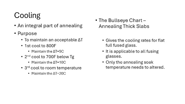
Annealing Strategies


This is a power point presentation I gave a few weeks ago to a group.  It may be of interest to others.  There is no commentary.


Rehearsing Special Cuts

For difficult cuts you can increase your confidence by rehearsing the score with a feather light movement of the cutter on the glass along the score line. Make any adjustments shown to be necessary by this rehearsal before beginning the score.

It is important to remember the basic scoring tips as they become even more important with difficult cuts:

  • Keep an even/constant speed during the scoring.
  • Keep a consistent pressure - less than 3kg/ 7 lbs is all the pressure required.
  • Make sure the cutter is vertical – eye the cutter from top to wheel to cut line.
  • Stand behind the direction of the cut line.
  • Use your body to turn, do not use the wrist or arm.
Start with the most difficult score first. Any break-outs or mistakes will not waste much work or glass.

Break out each score as you make it. You can store up trouble by making multiple scores before starting to break. The score lines can run across the main piece when breaking off the scored glass. Any inaccuracies will also be magnified by making all the scores before breaking.

More information is given in these blog posts:

Revised 30.12.24

Saturday, 28 December 2024

Slumping a Form Flat


There are a variety of reasons that you might want to make a formed piece flat again for another kind of slump or drape.  There are a variety of things to think about when preparing to make a shaped piece flat.  I am going to assume there are no large bubbles in the piece and there are posts on Large bubbles and Bubble at bottom  including the causes.

There are five groups of things to consider when contemplating flattening an already formed shape.

Shape/form
  • Shallow forms with no angles have the fewest difficulties.  Take it out of the mould, put it on the prepared shelf and fire to the slump temperature.  Observe when it is flat and proceed to the annealing.
  • Forms with angles or multiple curves are a little more difficult.  If the piece has stretched in some areas to conform to the mould, you will have some distortion in the pattern and possibly some thinner areas.  It should be easy to flatten pieces on a prepared shelf with the same schedule, but a slightly higher top temperature than in the previous slump.
  • Forms where the sides have pulled in will become flat, but continue to have curved sides.
  • Deep forms are possibly the most difficult.  The glass may have stretched, giving thin areas.  It may be that the process of flattening the glass will cause a rippled effect as the perimeter of the piece is a smaller size than the original footprint.  These deep forms are the least likely to flatten successfully.

Orientation
  • Which way up? Upside down or right side up?  Shallow forms are easiest to flatten by placing them right side up on a prepared shelf.  For deep or highly formed pieces, it may be best to put it upside down to allow the now higher parts to push the perimeter out if it is necessary.

Thickness
  • Thick glass will flatten more quickly than thin glass when using slower ramp rates, so you need to keep a watch on the progress of the work to avoid excess marking of the surface of the glass.
  • Very thin pieces are likely to develop wrinkles as they flatten.  Even if they do not, there will be thick and thin areas which might cause difficulty in subsequent slumping.
  • Tack fused pieces are likely to tend to flatten at different places and times due to the differences in thickness and therefore weight. This makes observation of the flattening process more important.

Temperatures
  • In all these processes, you should use the lowest practical temperature to flatten.  This means that you will need to peek at intervals to see when it is flat.
  • Your starting point for the top temperature to use will be about the same as  the original slump, normally.  The amount of time may need to be extended significantly. The reason for this is to avoid as much marking on the finished side as possible.
  • Shallow forms and thick pieces will flatten more quickly than others, so a lower temperature can be used.  You will still need to observe the progress of the flattening.
  •  Angled shapes and deep forms will need more heat and time than the shallower ones. 
  • Thin pieces may require more time than thick pieces.
  • Tack fused pieces need more attention and slow rates of advance to compensate for the differences in thicknesses.

Separators
  • Kiln washed shelves are usually adequate for flattening.
  • Thinfire or Papyros are needed when flattening upside down to ease any sliding necessary.
  • Powdered kiln wash or aluminium hydrate can be dusted over the kiln washed shelf when it is felt the form will need to slide on the shelf while flattening.

It may be that after all this, you feel it is not worth it to flatten.  It certainly is worth the effort, if only to learn about the characteristics of the form and its behaviour in reversing the slump or drape.

Devitrification

What is it? When does it happen? Why does it happen? These are frequent questions.

Dr. Jane Cook states that devitrification is not a category (noun), but a verb that describes a process. Glass wants to go toward devitrification; a movement toward crystallisation.*


Mild devitrification is the beginning of crystallisation on the surface of the glass. It can look like a dirty film over the whole piece or dirty patches. At its worst, the corners begin to turn up or a crackling can appear on a granular surface.  This is distinct from the effects from an unstable glass or the crizzling as in a ceramic glaze. Devitrification can occur within the glass, but normally is a surface effect as oxygen is required.

Differences in the surface of glass promotes precipitation of the crystal formation of silica molecules.  This fact means that two defences against the formation of crystals are smooth and clean surfaces. There are other factors at play also.  The composition of the glass has an effect on the probability of devitrification.  Opaque glass, lime, opalising agents, and certain colouring agents can create microcrystalline areas to "seed" the devitrification process.  One part of the composition of glass that resists devitrification is the inclusion of boron in the composition of the glass, acting as a flux.

Visible devitrification generally occurs in the range of approximately 720°C – 830°C/1330F - 1525F, depending to some extent on the type of glass.  This means that 
the project needs to be cooled as quickly as possible from the working (or top) temperature to the annealing point, which is, of course significantly below this range.

There is evidence to show that devitrification can occur on the heat up by spending too long in this devitrification range, and that it will be retained in the cooling. Normally this is not a problem as the practice in kilnforming is for a quick advance on the heat up through this range, causing movement in the glass and so working against any crystallisation.  The quick advance does not (and should not for a variety of reasons) need to be as fast as possible.  A rate of 300°C per hour will be sufficient, as time is required for devitrification to develop.


Medical research into using a glass matrix to grow bone has shown that devitrification begins around 650C/1200F, but only becomes visible after 700C/1290F.  This has implications for multiple slumps.  Devitrification is cumulative, so the devitrification that may have begun on the flat piece will be added to in the slumping process and may become visible.  For me this has appeared as a haze on the edge of the slumped piece.  Avoidance of this effect is by thorough cleaning of the piece before placing it in the mould.

The devitrification seen in typical studio practice results more often from inadequately cleaned glass than from excessive time at a particular temperature, up or down, through the devitrification range.  
It is often seen as a result of grinding edges to fit.  Even though the ground edge is cleaned, it may still be rough enough to promote devitrification.  The edge must be prepared for fusing by grinding to at least 400 grit (600 is better).  Alternatively, use a fine coating of clear powder to give a new surface to the whole piece.

Dr. Cook suggests three approaches to devitrification:*
Resistance through:
 - Schedules
 - Flux

Dealing with it:
 - Cold work
 - Acids
Embrace it:
 - Allow it
 - Use it

Other sources of information:
Temperature range for devitrification
Homemade devitrification solution
Frit to fill gaps
Low Temperature Kilnforming at Etsy and Bullseye


* From a lecture given by Dr. Jane Cook at the 2017 BECON

[entry revised 28.12.24]

Cleaning Materials and Solutions


You need to clean glass that is going into the kiln to avoid devitrification on the surfaces.  This can be a greater or lesser problem for different individuals.  It is probably related to the studio practice and the amount of oils in or on fingers.

The first things to consider in cleaning glass for kilnforming are what you are trying to eliminate from the glass, the chemical nature of glass, and how to avoid putting further contaminants on the glass.

Cleaning is to remove surface deposits
The sensitivity of glass to minor contamination is shown by the fact that the small amount of oil from your finger tips can provide sources of devitrification.  This means the glass needs to be really clean and free from any deposits.  You need to remove oils and dusts and anything you may have added during assembly to leave nucleation points for devitrification. This includes any minerals in the water used to clean the glass.

Avoid soaking in acids
Glass is an alkaline (or basic) material.  This means that acids can affect the surface of the glass – at the microscopic level – enough to provide those nucleation points for devitrification to develop.  An odd thing about the way vinegar attacks glass is that the more dilute it is, the more etching it does of the glass.  This has to do with the greater amount of oxygen to transfer from the vinegar water to the glass, leaving microscopic etching as the minerals encased in silica are released from the glass surface.  This is visible as mild dulling in the shine of the surface.

If acids are used to clean the glass, rinse immediately in an alkaline solution such as baking soda.  You need then to get rid of the chemical reaction products formed by the neutralisation of the acid.  This should be done by immediately rinsing with running clear water. Follow this with a polish dry using unprinted paper towels.

Cleaning with spirits
My recommendation is to avoid spirits, especially those with additives such as rubbing alcohol. The amount of oil that is to be removed from the glass is small, so application of large amounts of spirits is not necessary.  It is reported that some aggressive spirits may affect the surface of the glass by combining with the minerals or the silica of the glass – this is not proven. If you do use spirits make sure they are thoroughly cleaned off and polished dry.  It is all too easy to leave residues.

What can I use to clean the glass?

The simplest cleaner is water.  A drop or two of dish washing liquid can provide a break to the surface tension, allowing the water to flow smoothly over the whole surface.  Then polish dry with clean unprinted paper towels.  Often this will not be sufficient to clean all the oils and chemicals from the glass and the best alternative is to use isopropyl alcohol neat or diluted 1:1 with water.

In many areas, the public water supply is hard – i.e., has an appreciable level of minerals.  Calcium and iron are two common minerals in any water supply. Some water supplies have other additives such as chlorine, fluorine and other purifiers. Chlorine and fluorine react strongly with glass, so air drying is not a good choice in drying glass in areas where there are these chemicals in the water supply.  Iron is another strong reactor with glass.  In high iron areas it may make it difficult to use water as the cleaning element.

It is suggested that distilled water can be used instead of the public water supply.  Yes, it can.  But it is expensive and not necessary.  Instead there are a few commercial cleaning agents that work well.  In North America Spartan glass cleaner is recommended.  In Europe Bohle glass cleaner is recommended.  I use isopropyl alcohol as my final rinse.  

After applying these glass cleaners, you still must polish to squeaky clean and dry.

Revised 28.12.24

Breaks in Slumping - diagnosis


Diagnosis of breaks during slumping processes is often difficult because the temperature is not high enough to be able to apply the usual rule of 
  • sharp edges indicate breaks on the cool down; 
  • rounded edges indicate breaks on the heat up.

www.warm-glass.co.uk


This not a universally applicable diagnosis.

At low slump temperatures, the edges will be sharp in both a break on heating up, and on the way down in temperature.

The best test to determine when the break occurs is to observe periodically during the heat up.  You will be able to see if the piece breaks before the top temperature.  If it is whole at top temperature, the break occurred on the way down.

If you have been unable to observe the progress of the firing, you will need to diagnose when the break occurred from the clues left.  The test here is not whether the edges are rounded or sharp, because at normal slumping temperatures, the break will be sharp in both cases. 

If the break occurred before the top temperature, the pieces will shape separately as the will be on different parts of the mould. Therefore, If the pieces no longer fit together, the break was on the rise. If they do fit exactly, the break was on the way down.  Place the pieces very carefully together to see if they form part of a continuous curve.  If they do, the break was on the cool down.  If they almost  match, or do not match at all, then the break was on the rise in temperature.

In general, when the break is on the cool down, there has been an overhang of the flat glass onto the mould which causes the break.  But the most common break of a slumping piece is caused by a too quick rise in temperature.  The distance the pieces are apart will give an indication of the force of the break.  The farther apart the pieces are, the slower the ramp should be - either up or down.

For a flat 6mm piece, the slump temperature rise should be less than twp thirds as quick as the rise for the fusing.  If you have a tack fused piece to be slumped you should reduce the rate of advance to at least half of that for a smooth, flat piece of 6mm.  Thicker glass with tack fused elements will need to be even slower.


Revised 28.12.24

Friday, 27 December 2024

Characteristics of Some Glasses

This information has been taken from various sources. Some manufacturers may change the composition of their glasses or the published information about them from time to time. Therefore, this information can only be used as a guide. If the information about strain, annealing, and softening points is important, contact the manufacturer for the most accurate information.

The temperature information is given in Celsius.
Strain point – the temperature below which no annealing can be done.
Annealing point – the temperature at which the equalisation soak should be done before the annealing cool.
Softening point – the temperature at which slumping can most quickly occur.


Armstrong – Now made by Kokomo

Typical Borosilicate – nominal CoE 32
Strain point – 510 - 535C / 951 - 996F
Annealing point – ca. 560C/1041F
Softening point - ca. 820C/1509F

Blackwood OZ Lead – nominal CoE 92
Annealing point - 440C/825F

Blenko – nominal CoE 110
Annealing point – 495C/924F

Bullseye – nominal CoE 90

Transparents
Strain point - 493C/920F
Annealing point - (532C)  Note that Bullseye has changed this to 482C/900F for thick items
Softening point - 677C/1252F

Opalescents
Strain point - 463C/866F
Annealing point – (501C)  Note that Bullseye has changed this to 482C900F for thick items
Softening point - 688C/1272F

Gold Bearing
Strain point - 438C/821F
Annealing point - (472)   Note that Bullseye has changed this to 482C/900F for thick items
Softening point - 638C/1182F

Chicago – nominal CoE 92

Desag  Note that this glass is no longer produced
Artista – nominal CoE 94
Strain point – 480 - 510C / 897 - 951F
Annealing point – 515 - 535C / 960 - 996F
Softening point – 705 – 735C / 1302 - 1356F
Fusing range – 805 – 835C / 1482 - 1537

Float Glass (Pilkington UK)
Optiwhite
Strain point – 525 - 530C / 978 - 987F
Annealing point – 559C/1039F
Softening point – 725C/1338F

Optifloat
Strain point – 525 - 530C / 978 - 987F
Annealing point – 548C/1019F
Softening point – 725C/1338F

Float Glass (typical for USA) nominal CoE 83
Strain point - 511C/953F
Annealing point - 548C/1019F
Softening point – 715C/1320F

Float Glass (typical for Australia) nominal CoE 84
Strain point - 505-525C / 942 - 978F 
Annealing point – 540 -560C / 1005 - 1041F

HiGlass “GIN” range – nominal CoE 90
Annealing point - 535C/996F

Gaffer colour rod – nominal CoE 88

Gaffer NZ Lead – nominal CoE 92
Annealing point - 440C/825F

HiGlass
Annealing point - 495C/924F

Kokomo – nominal CoE 92 - 94

Cathedrals
Strain point - 467C/873F
Annealing point - 507C/946F
Softening point - ca. 565C/ca.1050F

Opal Dense
Strain point - 445C/834F
Annealing point - 477C/891F
Softening point – ca. 565C/1050F

Opal Medium
Strain point - 455C/834F
Annealing point - 490C/915F
Softening point – ca.565C/1050F

Opal Medium Light
Strain point - 461C/863F
Annealing point - 499C/931F
Softening point – ca.565C/1050F

Opal Light
Strain point - 464C868F
Annealing point - 502C/937F
Softening point – ca.565C/1050F

Kugler 
Clear – nominal CoE 96 +/- 2  (94-98)
softening point: - 694C/1281F
Annealing point: - 508C/946F
Strain point: - 485C/904F

Colours - nominal CoE 96 +/- 4 (92-100)
Annealing point: - 500C/932F
Strain point: - 460C-500C/860 -879F

Typical lead glass – nominal CoE 91

Lenox Lead – nominal CoE 94
Annealing point – 440C/825F

Merry Go Round – nominal CoE 92

Moretti/Effetre – nominal CoE 104
Strain Point: 448C/839F
Annealing Range: 493C – 498C / 920F - 929F
Softening Point: 565C/1050F

Pemco Pb83 – nominal CoE 108
Annealing point – 415C/780F

Reichenbach - 

nominal CoE 96 +/-2 (94 -98)

Annealing range; - 470C-530F/878F-986F; Ave 510C/950F

nominal CoE 104  no further information at present.


Schott Borosilicate (8330) nominal CoE 32
Annealing point - 530C/987F

Schott “F2” Lead – nominal CoE 92
Annealing point - 440C/825F

Schott “H” & “R6” rods - nominal CoE 90
Annealing point – 530C/987F

Schott “W” colour rod – nominal CoE 98

St Just
MNA
Strain point - ca.450C/843F
Annealing point – ca. 532C/ca. 991F

Spectrum
System 96 – nominal CoE 96
Transparents
Strain point – 476C  +/- 6C  /  890F +/- 11F
Annealing point – 513 +/- 6C  /  956C +/- 11F
Softening point – 680 +/- 6C  /  1257F +/- 11F
Opalescents
Annealing point – 505 -515C  /  942 - 960F

Spruce Pine 87 – nominal CoE 96
Annealing point – 480C/897F

Uroboros system 96 – nominal CoE 96

Transparents
Strain point - 481C/899F
Annealing point - 517C/964F

Opalescents
Strain point - 457C/855F
Annealing point - 501C/935F

Uroboros - nominal CoE 90

Transparents
Strain point - 488C/911F
Annealing point - 525C/978F

Opalescents
Strain point - 468C/875F
Annealing point - 512C/955C

Wasser - nominal CoE 89
Annealing point – 490C/915F

Wissmach
Wissmach 90
Annealing point - 483C/900F
Softening point - 688C/1272F
Full Fuse - 777+

Wissmach 96
Annealing point - 
483C/900F
Softening point - 688C/1272F

Full Fuse - 777+ / 1432+


Tuesday, 24 December 2024

Solder Alloys, 2

This is an updated version of a table on various possibly useful solders.
Solder Alloy  Composition  Solidus  Liquidus Uses
25/75 Sn/Pb 183C 266C general plumbing, car radiators

30/70 Sn/Pb 183C 256C general plumbing, car radiators

30/50/20 Sn/Pb/Zn 177C 288C economical solder for aluminium, Zinc and Cast iron

40/60 Sn/Pb 183C 238C brass, plumbing, car radiators

50/50 Sn/Pb 183C 216C general purpose, plumbing, not for gold, silver

50/48.5/1.5 Sn/Pb/Cu 183C 215C reduces copper erosion on irons

60/40 Sn/Pb 183C 190C electronics, good wetting, duller surface than 63/37

63/37 Sn/Pb 183C 183C eutetic, electronics, stainless steel, bright joints

62/37/1 Sn/Pb/Cu 183C 183C similar to 63/37 and reduces erosion on irons
90/10 Sn/Pb 183C 213C

95/5 Sn/Pb 238C 238C plumbing and heating

96.5/3/0.5 Sn/Ag/Cu 217C 220C recommended lead free for electronics 

95.8/3.5/0.7 Sn/Ag/Cu 217C 218C
wave and dip soldering

95.6/3.5/0.9 Sn/Ag/Cu 217C 217C
eutectic


95.5/3.8/0.7 Sn/Ag/Cu 217C 217C European preference for wave and dip soldering

96.5/3.5 Sn/Ag 221C 221C wide use, poor wetting, strong lead free joints, stainless steel

95/5 Sn/Ag 221C 254C strong, ductile joints on copper, stainless steel

94/6 Sn/Ag 221C 279C strong, ductile joints on copper, stainless steel

93/7 Sn/Ag 221C 302C strong, ductile joints on copper, stainless steel


Ag = Silver
Cd = Cadmium
Cu =Copper
PB = Lead
Sn = Tin
Sb = Antimony


Cutter Wheel Angles, 1

The Effects of Wheel Angles on Glass Cutting

The wheel of a glass cutter does not “cut” the glass. The objective is to create a crack or "fissure" along which we expect the glass to break when we bend it. The idea is to produce a fissure which is continuous, and of uniform depth, without creating a flaky score line full of loose glass chips. While the wheel angle is only one of several variables which influence the quality of the fissure, it is the best place to start. The other main variables are wheel diameter and cutting pressure.

The angle of a wheel is identified as the included angle to which the apex is honed. This means it is measured from one beveled face of the wheel around through the wheel to the other face. Thus the angle between the wheel and the glass on a 150° wheel will be 15° on each side.
When downward pressure is exerted on the wheel rolling along the glass, forces are created which radiate down and to the side trying to shear or separate the glass along the surface. These forces are in a downward direction with little angle to the side when an appropriate angled wheel is used. If these forces are great enough to overcome the inherent compressive conditions near the surface, a crack or fissure will be generated along the path of the wheel. The direction of these shearing forces is determined by the wheel angle.

A wheel with a large or blunt angle produces shearing forces that tend to be directed downward more than to the side. It would require a great deal more cutter pressure to create enough lateral force to overcome the compression in glass. This explains why a cutter requires more pressure as it gets older. The apex tends to flatten so its effective angle becomes greater.

With a very sharp wheel angle, the shear forces are directed more parallel to the surface of the glass. This might suggest it is easier to produce a fissure with a sharp wheel than a dull one. The shear forces are directly opposing the compressive condition near the surface of the glass therefore, requiring less downward pressure to make a crack. But a sharp wheel tends to cause chips and a flaky score. Also, when the shear forces run close to the surface of the glass they are more likely to cause a lateral crack which then breaks out to the surface, creating a chip. You can see these chips leap out of the glass a short time after scoring. Again, the compressive condition of glass near the surface literally squeezes the fissure closed, spitting out loose chips. They can be seen lying on top of the glass.

Part 2

Based on information from the Fletcher Terry Company.

See also wheel angles

Revised 23.12.24

Cutter Wheel Angles, 3

The effect of glass thickness on cutting

Most of the thicker glass being used today is produced by the "float" method. In this process the glass travels horizontally from the furnace, through a molten tin bath, through annealing lehrs, then continues on rollers where it is inspected, scored and broken into the sizes required. The thickness generally dictates how fast the ribbon of glass moves. The thicker the glass, the slower it is processed and the more effective the annealing. This applies to thicker art glass too.

The key to subsequent cutting float glass is the annealing cycle. Thicker glass tends to have less compression at the surface and tension in the interior. As a result, the glass cutting wheel encounters less resistance to producing a fissure with the shearing forces. However, this means the glass surface will chip more readily. Therefore, a larger wheel angle is required to prevent chipping. It is also common practice to use a larger diameter wheel and larger angle so the fissure can be driven deeper without chipping.

Part 1

Prepared from information provided by the Fletcher-Terry company.