Sunday, 24 July 2022

Phase Separation and Crystallization in Glass


From the Mo-Sci Corporation Blog:

Posted by  


While historically a source of problems for glass producers, the phenomenon of phase separation is now known to offer advantages in the production of certain materials such as glass ceramics and porous glasses. Whether desirable or undesirable, understanding and controlling phase separation during the glass manufacturing process is crucial. In this article, we explore the basics of phase separation and how it can be manipulated to create advanced materials for various applications.

What is phase separation?

In physics and chemistry, the word “phase” refers to a region of a material that is chemically uniform and physically distinct. Phase separation, which typically occurs in liquids, is where a homogeneous mixture separates into two or more of these phases. For example, a mixture of water and oil at room temperature will naturally “phase separate” into a distinct phase consisting of pure oil, and another consisting of pure water. We can say that such a mixture is “immiscible.”

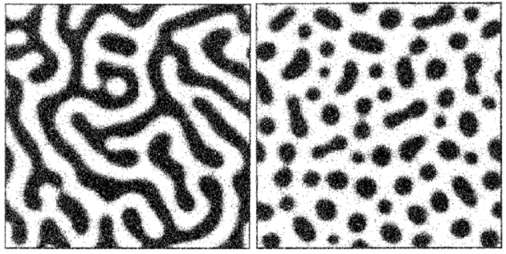
The morphology of this phase separation can vary depending on the relative concentration of both components. If the mixture is predominantly water, the oil phase will take the form of distinct (or “discontinuous”) droplets dispersed throughout an interconnected (or “continuous”) water phase. If the mixture is predominantly oil, the opposite will take place. At roughly equal proportions of oil and water, each phase will tend to be continuous.

Phase Separation in Glass

Phase separation commonly occurs in glass melts. Borosilicate glass – which contains both silica and borate as network formers – is a well-studied example.1,2

Unlike our water/oil example, phases in glass melts are not necessarily chemically pure. Borosilicate glass, for example, will typically undergo phase separation into a “borate-rich” phase and a “silica-rich” phase, with both phases containing different proportions of each network former. In addition, the morphology of separated phases in glass can vary. While it is possible for droplet-like phases to form via classical nucleation and growth, spontaneous “spinodal” phase separation can result in the formation of intertwined tendril-like continuous phases.3

Example of spinodal decomposition next to nucleation
On the left, spinodal decomposition produces “tendrils” of different phases. On the right, nucleation produces droplets of the darker phase within the lighter phase. (Gebauer et al., 2014)4

This phase separation, which occurs at high temperatures in the molten glass, persists and “freezes in” when the glass is cooled into a solid. If both phases are vitrifiable, they may form glasses after cooling (this is called a glass-glass phase separation). However, if one phase is prone to crystallization, the mixture can cool into a glass-crystal phase-separated solid.5

Phase separation in glasses was long seen as undesirable – and for many applications, it still is.6 The existence of different phases modifies the physico-chemical properties of glass melts, making it difficult to mold and reduce the quality of the final glass.

The physics of phase separation in glass-forming materials is complex, and even today the specifics are subject to intense debate.7 However, glass manufacturers nonetheless determined ways of avoiding or minimizing phase separation during glass manufacturing.

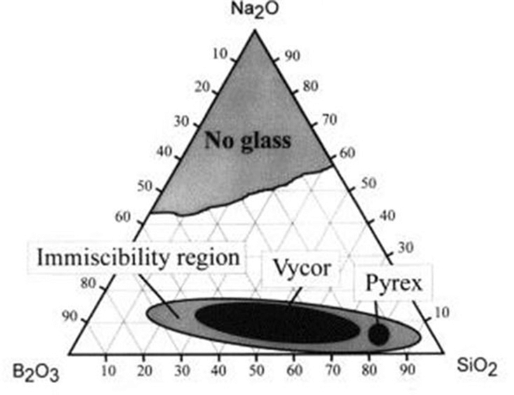
Typically, this is achieved by tailoring the composition of glass melts, with phase separation only occurring for specific compositions. In a Na2O–B2O3–SiO2 glass system, for example, the following ternary phase diagram shows the immiscibility region in which phase separation will occur.

Simplified ternary phase diagram for the Na2O–B2O3–SiO2 system. (Bartl et al., 2001)8

Phase separation (and subsequent crystallization) can also be controlled by the addition of glass modifiers, and by varying heat treatment and cooling rates.9

Controlling and Exploiting Phase Separation in Glass

Note that within the immiscibility region in the diagram above, two common commercial glass compositions are labeled. Indeed, it’s now understood that phase separation ­offers advantages in certain applications. Today, heterogeneous phase-separated glasses cover a broad range of commercial applications, including Pyrex®, Vycor® opal glass, porous glass, and glass ceramics.

Glass-ceramics are a class of polycrystalline materials that share many properties with both glasses and ceramics, ideally providing the moldability of glasses with various special properties (such as high strength) of ceramics. Glass-ceramics are produced by the formation of crystal phases within an amorphous base glass (i.e., crystal-glass phase separation). Engineering glass-ceramics depends on controlling crystallization within the base material.10


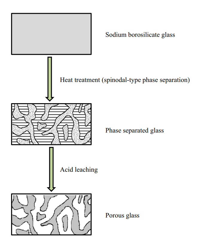
Another application of controlled phase separation is in the production of porous glasses. Porous glasses are typically high-silica glasses that contain pores with a specific size distribution, ranging from angstrom to millimeter scales. Porous glasses are commonly produced from phase separation of alkali borosilicate glass, in which the mixture undergoes spinodal phase separation following heat treatment to yield two continuous phases.11 Following phase separation, the alkali-rich borate phase can be dissolved in acid and removed from the solid. This leaves a highly pure and porous silica glass “skeleton.”

Schematic showing the formation of porous glass from a phase-separated alkali (sodium) borosilicate mixture. (Hasanuzzaman et al 2016)11

Porous glass exhibits improved mechanical and thermal stability compared to ordinary bulk glass, making it a popular alternative to fused quartz which is comparatively difficult to form. Other applications make use of the pores themselves: such as filitering materials, catalyst supports, and targeted drug delivery.12–16 Mo-Sci is a world-leading provider of advanced glasses for healthcare, electronics and engineering applications. We offer a range of glass-ceramic seals and porous glass solutions, as well as providing custom solutions for virtually any glass application. Contact us for more information.

References and Further Reading

  1. Charles, R. J. Phase Separation in Borosilicate Glasses. Journal of the American Ceramic Society 47, 559–563 (1964).
  2. Möncke, D., Ehrt, D. & Kamitsos, E. Spectroscopic study of manganese-containing borate and borosilicate glasses: Cluster formation and phase separation. Physics and Chemistry of Glasses – European Journal of Glass Science and Technology Part B 54, 42–51 (2013).
  3. Bergeron, C. G. & Risbud, S. H. Introduction to Phase Equilibria in Ceramics. (American Ceramic Society, 1984).
  4. Gebauer, D., Kellermeier, M., Gale, J., Bergström, L. & Cölfen, H. Pre-nucleation clusters as solute precursors in crystallisation. Chemical Society reviews 43, 2348–2371 (2014).
  5. Schuller, S. Phase separation in glass. (2018).
  6. Morey, G. W. The Properties of Glass. (Books on Demand, 1954).
  7. Da Vela, S. et al. Interplay between Glass Formation and Liquid–Liquid Phase Separation Revealed by the Scattering Invariant. J. Phys. Chem. Lett. 11, 7273–7278 (2020).
  8. Bartl, M. H., Gatterer, K., Fritzer, H. P. & Arafa, S. Investigation of phase separation in Nd3+ doped ternary sodium borosilicate glasses by optical spectroscopy. Spectrochimica Acta Part A: Molecular and Biomolecular Spectroscopy 57, 1991–1999 (2001).
  9. Liu, S., Zhang, Y. & Yue, Y. Effect of cooling rate on crystallization in an aluminophosphosilicate melt. Physics and Chemistry of Glasses – European Journal of Glass Science and Technology Part B 52, (2011).
  10. Control of nucleation in glass ceramics | Philosophical Transactions of the Royal Society of London. Series A: Mathematical, Physical and Engineering Sciences. https://royalsocietypublishing.org/doi/10.1098/rsta.2002.1152.
  11. Hasanuzzaman, M., Rafferty, A., Sajjia, M. & Olabi, A.-G. Production and Treatment of Porous Glass Materials for Advanced Usage. in Reference Module in Materials Science and Materials Engineering (Elsevier, 2016). doi:10.1016/b978-0-12-803581-8.03999-0.
  12. Hammel, J. J. & Allersma, T. United States Patent | Thermally stable and crush resistant microporous glass catalyst supports and methods of making. 341–341 (1975).
  13. Jungbauer, A. Chromatographic media for bioseparation. Journal of Chromatography A 1065, 3–12 (2005).
  14. Sotomayor, P. T. et al. Construction and evaluation of an optical pH sensor based on polyaniline-porous Vycor glass nanocomposite. in Sensors and Actuators, B: Chemical vol. 74 157–162 (2001).
  15. Takahashi, T., Yanagimoto, Y., Matsuoka, T. & Kai, T. Hydrogenation activity of benzenes on nickel catalysts supported on porous glass prepared from borosilicate glass with small amounts of metal oxides. Microporous Materials 6, 189–194 (1996).
  16. Using Porous Glass Microspheres for Targeted Drug Delivery Mo-Sci Corporation. https://mo-sci.com/porous-glass-microsphers-targeted-drug-delivery/.

linkedin sharing button Share
twitter sharing button Tweet
facebook sharing button Share

Wednesday, 20 July 2022

Slump Shrinkage


Glass on rectangular moulds often does not maintain a straight edge.  It pulls in and tends toward the “dog boning” of fused single layer glass even if not so dramatic.

Explanation

The reasons for the pull-in on rectangular moulds are similar to those for dog boning. You should note that squares are special cases of the general class of rectangles. The discussion here applies squares just as much as to rectangles.

If you grid the rectangular glass, it illustrates that the glass in the corners is moving in two directions.  It is moving and slightly stretching into the mould.  At the same time, it is trying to compress into the corner of the mould.  The glass along the sides are moving in only one direction – stretching only slightly and moving toward the bottom of the mould.

There is more compression than stretching in the corners. The sides have only to move in one direction and experience no compression and so move toward the bottom more easily.

Such is my explanation of the experience. 

Avoidance

The real question then is how to prevent this pull-in that is so commonly experienced on rectangular moulds with no rims.  One way would be to avoid such moulds altogether.  This of course, is not practical, so some approaches to compensate or avoid the problem are needed.

It is possible to compensate for this pull-in by slumping a rectangle with slightly bulging sides.  Rather than a regular rectangle, you create one with slightly outwardly curved sides.  Getting the exact amount of curve will be difficult and achieved only after a number of experiments.

The opposite compensation would be to round the corners of the glass, so there will not be so much glass to fit into the corners of the mould.  This again will require experimentation to achieve a predictable result.  And it often would interfere with the appearance of the final piece.

The easiest, but not always successful, way to prevent the pull-in is to alter the scheduling for slumps on such moulds.  It is a well-known property of glass that it does not have a single softening point, but progressively softens with temperature and time.  You can take advantage of this by using four elements in combination. 

·        Use a slow rate of advance to the slump temperature, to allow the glass to evenly absorb a lot of heat on the way to slumping. 
·        Use a low slumping temperature  This may be as much as 30°C less than your usual temperature.
·        Use a long soak at the slumping temperature.  This may be hours.  You need to allow the glass to slump into the mould without stretching.  To avoid stretching, you need a low temperature.  At low temperatures, the glass requires a lot of time to conform to the mould.
·        Observe at 10- to 15-minute intervals once the slumping temperature is achieved.

These processes are outlined in a blog post on dog boning.  Further information is available in the ebook: Low Temperature Kiln Forming.


Avoidance of pull-in of the glass on rectangular moulds is related to scheduling and observance.  There are some compensations that can be tried, but require considerable experimentation to be successful.

Sunday, 17 July 2022

Building with Recycled Glass

Future cities could be 3D printed – using concrete made with recycled glass 

From: The Conversation, February 28, 2022 12.39pm GMT

Authors


3D printed concrete may lead to a shift in architecture and construction. Because it can be used to produce new shapes and forms that current technologies struggle with, it may change the centuries-old processes and procedures that are still used to construct buildings, resulting in lower costs and saved time.

However, concrete has a significant environmental impact. Vast quantities of natural sand are currently used to meet the world’s insatiable appetite for concrete, at great cost to the environment. In general, the construction industry struggles with sustainability. It creates around 35% of all landfill waste globally.

Our new research suggests a way to curb this impact. We have trialled using recycled glass as a component of concrete for 3D printing.

Concrete is made of a mix of cement, water, and aggregates such as sand. We trialled replacing up to 100% of the aggregate in the mix with glass. Simply put, glass is produced from sand, is easy to recycle, and can be used to make concrete without any complex processing.

Our mission is to share knowledge and inform decisions.

Demand from the construction industry could also help ensure glass is recycled. In 2018 in the US only a quarter of glass was recycled, with more than half going to landfill.

Building better

We used brown soda-lime beverage glass obtained from a local recycling company. The glass bottles were first crushed using a crushing machine and then the crushed pieces were washed, dried, milled, and sieved. The resulting particles were smaller than a millimetre square.

The crushed glass was then used to make concrete in the same way that sand would be. We used this concrete to 3D print wall elements and prefabricated building blocks that could be fitted together to make a whole building.

Grey concrete structure
A building envelope prefabricated using the 3D printing process. Mehdi ChouganAuthor provided

If used in this way, waste glass can find a new life as part of a construction material.

The presence of glass does not only solve the problem of waste but also contributes to the development of a concrete with superior properties than that containing natural sand.

The thermal conductivity of soda-lime glass – the most common type of glass, which you find in windows and bottles – is more than three times lower than that of quartz aggregate, which is used extensively in concrete. This means that concrete containing recycled glass has better insulation properties. They could substantially decrease the costs required for cooling or heating during summer or winter.

Improving sustainability

We also made other changes to the concrete mixture in order to make it more sustainable as a building material, including replacing some of the Portland cement with limestone powder.

Portland cement is a key component of concrete, used to bind the other ingredients together into a mix that will harden. However, the production of ordinary Portland cement leads to the release of significant amounts of carbon dioxide as well as other greenhouse gases. The cement production industry accounts for around 8% of all carbon dioxide emissions in the environment.

Limestone is less hazardous and has less environmental impact during the its production process than Portland cement. It can be used instead of ordinary Portland cement in concrete for 3D printing without a reduction in the quality of the printing mixture.

3D printed layers of a wall element. Mehdi ChouganAuthor provided

We also added lightweight fillers, made from tiny hollow thermoplastic spheres, to reduce the density of the concrete. This changed the thermal conductivity of the concrete, reducing it by up to 40% when compared with other concrete used for 3D printing. This further improved the insulation properties of the concrete, and reduced the amount of raw material required.

Using 3D printing technology, we can simply develop a wall structure on a computer, convert it to simple code and send it to a 3D printer to be constructed. 3D printers can operate for 24 hours a day, decrease the amount of waste produced, as well as increase the safety of construction workers.

Our research shows that an ultra-lightweight, well insulated 3D building is possible – something that could be a vital step on our mission towards net zero.

Wednesday, 13 July 2022

Ceramic Drape Moulds

Characteristics of materials

One of elements you need to consider in selecting a mould for draping is the characteristics of the ceramic material in relation to the glass being draped.  

Ceramic

Ceramic materials have what are called inversions. These are  points at which the ceramic has a quick change in expansion both on the heat up and cool down.  The two major ones are cristobalite inversion temperature at around 225°C and the quartz inversion at about 570°C.  The Crystobalite inversion is a sudden change of about 2.5% and the quartz is a sudden change of 1%.  These are very sudden and dramatic changes in comparison to the average of around 0.1% over the temperature range of 570°C to 800°C.  The crystobalite inversion does not occur until ca. 225°C.  This means that the whole structure of the ceramic is contracting less than the glass – exhibiting a CoE of ca. 66 rather 90 to 96.

Ceramic drape mould from Creative Glass Guild

Glass

We are used to saying glass expands and contracts at a standard rate, depending on the glass this may be a CoE of 83 to one of 104.  This is not the case.  The coefficient is an average calculated between 20°C and 300°C.  If you change the temperature range, the coefficient will also change.  And if you look at the range 570°C to 580°C you find the CoE is around 500.  This means that as the glass cools into the annealing range, it is contracting about 7 times faster than the ceramic. 

This dramatic difference in contraction means that the glass is attempting to crush the ceramic by enclosing it tightly.  Sometimes it does it so strongly that the strength of the glass is exceeded, and it breaks.

Possibilities

It is possible to drape over ceramic in certain conditions.

Influence of draft

The term “draft” indicates the slope of the sides of the form.  The steeper the sides, the more likely the glass is to trap the ceramic mould.  To be useful, the draft of the mould needs to be sufficient for the glass to slide upwards on the mould as it cools. This means the mould needs smooth sides and be well covered with a separator.

Compensations

You can compensate for steep drafts by wrapping the ceramic form in 3mm refractory fibre paper.  You can bind this with high temperature wire to ensure it stays throughout the firing. The fibre paper can be compressed and so provides a cushion between the rapidly contracting glass and the slowly contracting ceramic.

These need a circle of 3mm fibre paper over the open top of the kiln posts that have no draft at all before use. Of course, they need to have a circular piece of fibre paper over the hole in the post.


The use of ceramic forms to drape over requires care about the draft of the ceramic or addition of a cushion to avoid the greater contraction of the glass than the ceramic grabbing the mould so tightly it cannot be removed.