Wednesday, 20 July 2022
Slump Shrinkage
Explanation
Avoidance
Sunday, 17 July 2022
Building with Recycled Glass
Future cities could be 3D printed – using concrete made with recycled glass
From: The Conversation, February 28, 2022 12.39pm GMT
Authors
 Seyed Ghaffar
Associate Professor in Civil Engineering and Environmental Materials, Brunel University London
 Mehdi Chougan
Marie Skłodowska-Curie Research Fellow, Brunel University London
 Pawel Sikora
Associate professor in Civil and Environmental Engineering, West Pomeranian University of Technology in Szczecin
3D printed concrete may lead to a shift in architecture and construction. Because it can be used to produce new shapes and forms that current technologies struggle with, it may change the centuries-old processes and procedures that are still used to construct buildings, resulting in lower costs and saved time.
However, concrete has a significant environmental impact. Vast quantities of natural sand are currently used to meet the world’s insatiable appetite for concrete, at great cost to the environment. In general, the construction industry struggles with sustainability. It creates around 35% of all landfill waste globally.
Our new research suggests a way to curb this impact. We have trialled using recycled glass as a component of concrete for 3D printing.
Concrete is made of a mix of cement, water, and aggregates such as sand. We trialled replacing up to 100% of the aggregate in the mix with glass. Simply put, glass is produced from sand, is easy to recycle, and can be used to make concrete without any complex processing.
Our mission is to share knowledge and inform decisions.
Demand from the construction industry could also help ensure glass is recycled. In 2018 in the US only a quarter of glass was recycled, with more than half going to landfill.
Building better
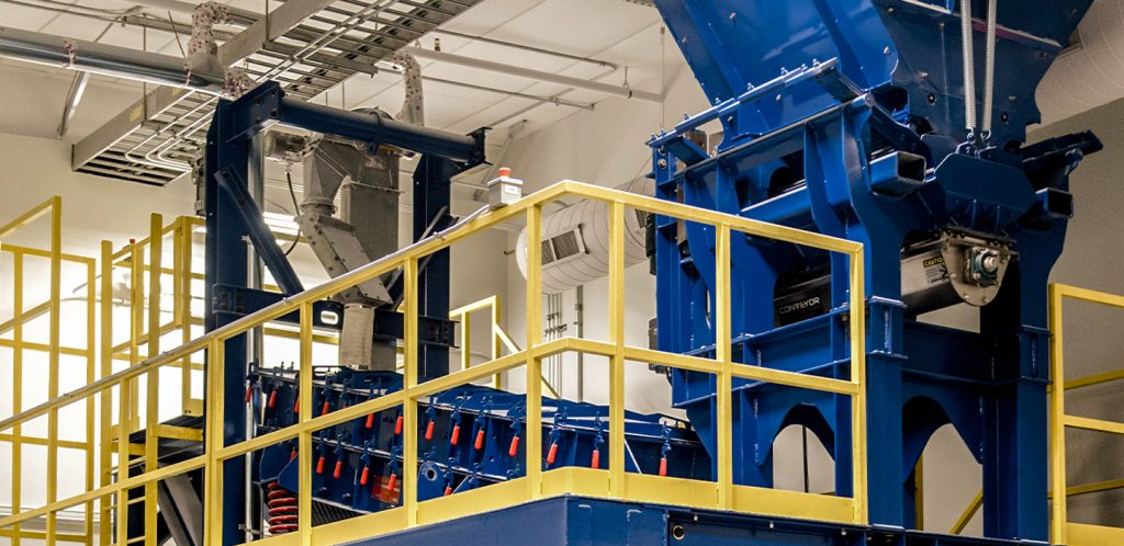
We used brown soda-lime beverage glass obtained from a local recycling company. The glass bottles were first crushed using a crushing machine and then the crushed pieces were washed, dried, milled, and sieved. The resulting particles were smaller than a millimetre square.
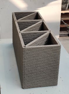
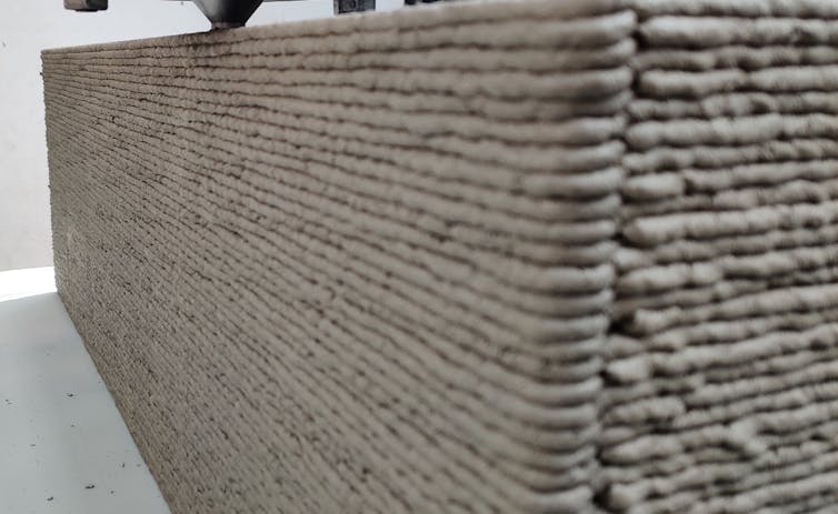
The crushed glass was then used to make concrete in the same way that sand would be. We used this concrete to 3D print wall elements and prefabricated building blocks that could be fitted together to make a whole building.

If used in this way, waste glass can find a new life as part of a construction material.
The presence of glass does not only solve the problem of waste but also contributes to the development of a concrete with superior properties than that containing natural sand.
The thermal conductivity of soda-lime glass – the most common type of glass, which you find in windows and bottles – is more than three times lower than that of quartz aggregate, which is used extensively in concrete. This means that concrete containing recycled glass has better insulation properties. They could substantially decrease the costs required for cooling or heating during summer or winter.
Improving sustainability
We also made other changes to the concrete mixture in order to make it more sustainable as a building material, including replacing some of the Portland cement with limestone powder.
Portland cement is a key component of concrete, used to bind the other ingredients together into a mix that will harden. However, the production of ordinary Portland cement leads to the release of significant amounts of carbon dioxide as well as other greenhouse gases. The cement production industry accounts for around 8% of all carbon dioxide emissions in the environment.
Limestone is less hazardous and has less environmental impact during the its production process than Portland cement. It can be used instead of ordinary Portland cement in concrete for 3D printing without a reduction in the quality of the printing mixture.

We also added lightweight fillers, made from tiny hollow thermoplastic spheres, to reduce the density of the concrete. This changed the thermal conductivity of the concrete, reducing it by up to 40% when compared with other concrete used for 3D printing. This further improved the insulation properties of the concrete, and reduced the amount of raw material required.
Using 3D printing technology, we can simply develop a wall structure on a computer, convert it to simple code and send it to a 3D printer to be constructed. 3D printers can operate for 24 hours a day, decrease the amount of waste produced, as well as increase the safety of construction workers.
Our research shows that an ultra-lightweight, well insulated 3D building is possible – something that could be a vital step on our mission towards net zero.
Wednesday, 13 July 2022
Ceramic Drape Moulds
Characteristics of materials
Ceramic
 |
| Ceramic drape mould from Creative Glass Guild |
Glass
Possibilities
Influence of draft
Compensations
Sunday, 10 July 2022
Bioactive vs. Biocompatible: What’s the Difference?
Bioactive vs. Biocompatible: What’s the Difference?
Posted Krista Grayson on Dec 1, 2021

The study of biomaterials — substances that are engineered to interact with biological systems for medical purposes — is a relatively new field, but one that has already produced a number of valuable discoveries and treatments.
Over the last few decades, the field has grown rapidly; and, with it, the list of new terms used to describe biomedical devices and materials. In this article, we take a look at two of the most common adjectives in the field, bioactive and biocompatible, and how they are used to describe a range of highly specialized materials.
Essentially, the term biocompatible is used to describe any material which is well-tolerated by the biological system it comes into contact with. At a minimum, most biocompatible materials are chemically inert. In practice, biocompatibility for a given application may depend on any number of other characteristics such as mechanical strength, elastic modulus, or adhesion with the surrounding cellular matrix. It is important to note that biocompatibility is application-specific: a material that is deemed biocompatible in one specific use case may not be biocompatible in another.
Bioactive materials go a step further – these are materials that produce some kind of local physiological response, typically through physical or chemical action. A common example of a bioactive material is bioactive glass: typically silicate-based glass-ceramic materials that are often degradable within the body. Used for bone repair, ion exchange at the surface of bioactive glass leads to the formation of bone-like hydroxyapatite, around which natural bone will readily grow.1 In this way, bioactive glass can actively stimulate the regeneration of bone within a patient.
The term “bioactive” is the opposite of “bioinert”, a word that refers to materials that don’t produce a physiological reaction.
Definitions and Distinctions
If we had to pick “official” definitions of “biocompatible” and “bioactive”, it would probably be those offered by The International Union of Pure and Applied Chemistry (IUPAC), a world authority on standardized scientific nomenclature.2
Bioactive: “Qualifier for a substance which provokes any response from a living system”. IUPAC also notes that the term is often used positively, i.e., to reflect a beneficial change.
Biocompatibility: “The ability to be in contact with a living system without producing an adverse effect.”
These definitions seem simple enough, but there are some subtleties that often cause confusion. These can be cleared up by thinking about how we apply the terms to a very familiar medical device: a contact lens.
Biocompatibility without Bioactivity
Modern contact lenses are made from soft, inert synthetic polymers known as silicone hydrogels. Silicone hydrogel contact lenses are wettable, permeable to oxygen, and cause minimal irritation to the tissues of the eye. We can confidently say, then, that modern contact lenses are highly biocompatible when used properly.
But is a contact lens bioactive? Although a contact lens modifies the light as it enters the eye (resulting in improved vision), the contact lens does not produce a local physiological response with the eye tissue. Thus, we can’t refer to an ordinary contact lens as bioactive.
Note also that “biocompatible” is typically used only in reference to materials, while the term “bioactive” is used to refer to materials or drugs. So, a drug that is tolerated well and without negative side effects would not typically be described as “biocompatible” even though it meets the IUPAC definition.
Mechanisms of Bioactivity
The mechanisms by which bioactivity can occur are numerous and often complex.3 Attempts to engineer bioactive materials often involve emulating intra-cellular signaling, using coatings of proteins or peptides to modulate cell interactions.
There are also many bioactive materials – largely within the category of bioactive glasses and ceramics – which produce a local physiological response through the exchange of simple ions such as silver, fluoride, and calcium.4 These “therapeutic ions” can activate, inhibit or enhance a huge array of cellular pathways, resulting in effects such as antibacterial activity, and stimulation of bone and blood vessel formation.
As research continues and scientists learn more about how different materials can influence cellular processes, we can expect more biocompatible and bioactive materials to find their way into mainstream medical treatment.
Mo-Sci has extensive experience in the manufacture of bioactive glasses. We produce standard compositions, such as 45S5, S53P4, and 13-93, and can also research, develop, and manufacture glass that is customized to fit your application. Contact us to see how we can help with your next product.
References and Further Reading
- Ferraris, S. et al. Bioactive materials: In vitro investigation of different mechanisms of hydroxyapatite precipitation. Acta Biomaterialia 102, 468–480 (2020).
- Vert, M. et al. Terminology for biorelated polymers and applications (IUPAC Recommendations 2012). Pure and Applied Chemistry 84, 377–410 (2012).
- Meyers, S. R. & Grinstaff, M. W. Biocompatible and Bioactive Surface Modifications for Prolonged In Vivo Efficacy. Chem. Rev. 112, 1615–1632 (2012).
- Baino, F., Hamzehlou, S. & Kargozar, S. Bioactive Glasses: Where Are We and Where Are We Going? JFB 9, 25 (2018).
Wednesday, 6 July 2022
Grinding direction
Sunday, 3 July 2022
Glass Milling Equipment and Techniques
Glass Milling Equipment and Techniques
Posted Krista Grayson on Aug 26, 2021

Milling is an effective top-down process for producing glass powders with particle sizes ranging from nanoscale to micron-size. This article provides a guide to the various types of milling processes used by Mo-Sci to produce our range of specialty glass powders.
Alongside microspheres and ingots, one of the primary forms in which Mo-Sci provides glass is as a powder. Powdered glass has numerous applications throughout research and industry. For example, glass nanofillers offer unique advantages in developing composite materials for medical and dental prosthetics.1,2 Such composites are not only incredibly strong, but exhibit superior biocompatibility due to their surface roughness, hydrophobicity, and chemical inertness.
While glass powders and nanofillers can be produced via “bottom-up” methods such as the sol-gel process, such techniques are not always practical, especially when producing glass particles with complex compositions.3 In these situations, a “top-down” solution is preferred: larger particles of glass can simply be broken down into smaller particles in a process known as milling.
Note that in the world of machining, “milling” has two meanings: it can refer either to grinding (e.g., using a ball mill) or cutting (e.g., using a CNC mill). Here, we’re strictly using the term in the former sense.
Glass Milling Processes
Jaw Crusher
A jaw crusher produces the coarsest grind out of any of the processes in this list. Much like a nutcracker, a jaw crusher uses direct application of compressive force between two mechanical “jaws” to fracture solid materials. The jaws are typically arranged vertically so that the gap between them narrows as material falls through the system. The particle size decreases as the material moves down through the crusher. Crushed material escapes through the narrow gap at the bottom between the jaws after it has been processed. Jaw crushers are heavy-duty machines often used for mining and quarry applications, and are suitable for continuous use with materials across a wide range of hardness. Jaw crushers are typically used to process larger fragments of material and are not capable of fine grinding. They may be used as a preliminary step before more controlled grinding in a ball mill or jet mill.
Hammer Mill
With more precision than a jaw crusher, a hammer mill (or hammer crusher) can crush aggregate material into smaller particles using hammers. Commonly used for processing papers, organic waste, and foodstuffs such as grain and fruit; hammer mills can also be used to produce glass powder. Available in configurations with one or several rows of hammers, hammer mills are high-durability devices capable of coarse grinding.
Ball Mill
Ball milling is one of the most commonly used techniques for milling glass, thanks to its adaptability and relatively low cost. A ball mill for glass processing consists of a rotating or vibrating ceramic-lined drum, inside which are a number of balls that act as the grinding medium. These can be made from a variety of hard and durable materials such as alumina or zirconia. Glass is added to the drum, and the continuous impact and attrition between the balls and the glass as the drum rotates breaks the glass down into small particles.
Ball mills are supremely versatile, they exist in a wide range of sizes, can perform wet or dry milling, and can accommodate a wide range of different grinding media. Ball mills are suitable for either batch or continuous processing, and grind size can be controlled by changing the diameter size of the balls. Industrial ball mills may be used to coarsely crush relatively large pieces of material, whereas lab-grade ball mills are capable of finely milling glass to micron level and below. So-called “high energy” ball milling can even be used to reliably grind the material into nanoscale particles.4
Centrifugal Mill
Most centrifugal mills lie firmly in the realm of labware. Inside a centrifugal mill, shearing action between a rotor and a fixed sleeve breaks material down in a relatively well-defined manner. High rotational speeds (up to several tens of thousands of RPM) enable fast and finely controlled grinding of small batches of material, often using sieves to enable the extraction of particles with sizes in the tens of microns region.
Jet Mill
Another precision piece of equipment, a jet mill uses a high-velocity flow of gas or compressed air to cause glass particles to collide with each other inside a chamber. A process known as cyclonic separation enables particles to leave the gas stream once they have reached a sufficiently small size. Consequently, jet mills can continue milling particles of glass until they reach the desired size, resulting in a glass powder with very little variation in particle size.5 Like ball mills, jet mills are capable of grinding glass powder down to sub-micron particle sizes.
Milled Glass Powders from Mo-Sci
At Mo-Sci, we are experienced in the use of all of these milling methods to produce a wide variety of specialty glass powders, including those made from complex formulations which are difficult to find elsewhere. As well as using different types of mills, we make use of various milling media (such as alumina, zirconia and yttria-stabilized zirconia (YSZ)), and perform wet milling in water or alcohol to achieve superior results.
To find out more about our capabilities in the specialty glass powders market, get in touch with the Mo-Sci team today.
References and Further Reading
- Velez, M. et al. Processing of yttrium aluminosilicate (YAS) glasses for dental composites. Cerâmica 57, 1–9 (2011).
- Erol-Taygun, M., Zheng, K. & Boccaccini, A. R. Nanoscale Bioactive Glasses in Medical Applications. Int J Appl Glass Sci 4, 136–148 (2013).
- Vital, A. et al. Ultrafine comminution of dental glass in a stirred media mill. Chemical Engineering Science 63, 484–494 (2008).
- Yang, L. 2 – Nanotechnology-enhanced metals and alloys for orthopedic implants. in Nanotechnology-Enhanced Orthopedic Materials (ed. Yang, L.) 27–47 (Woodhead Publishing, 2015). doi:10.1016/B978-0-85709-844-3.00002-1.
- Wachtman, J. B. Materials and Equipment – Whitewares Manufacturing. (John Wiley & Sons, 2009).


