Sunday, 15 May 2022

Using Silver-Releasing Glass to Reduce Bioburden


Using Silver-Releasing Glass to Reduce Bioburden

Posted  on 


Silver has been used for wound management for over 200 years, and its anti-microbial properties have been known since the 19th century.1 Although its direct use in the treatment of wounds fell out of favor when antibiotics were introduced, it continued to see applications in treatment for burns and other conditions on the surface of the body.

Recently, interest in silver has been renewed following research involving the use of silver with bioactive glasses that are implanted directly into the body. The unique properties of the glass and silver material allow it to be deployed in areas where antibiotics cannot reach; while the glass containment also allows more control over the concentration of silver ion released in specific areas.

Challenges with antibiotic resistance

A serious problem in all countries around the world is the rise of antibiotic-resistant bacteria that can cause issues for patients before, during, and after surgery. This includes strains such as methicillin-resistant Staphylococcus aureus (MRSA), that form biofilms on hospital equipment and surgical implants, increasing the bioburden on these surfaces.2

This is a particular problem for surgical implants: medical implant failure is commonly caused by infections resulting from bacteria living on implant surfaces. Due to the position of the implants and nature of the bacteria, these biofilms can be difficult to eliminate using antibiotics alone and treatment may require surgical removal.

How does silver impact bacteria?

One method of inhibiting the growth of antibiotic-resistant strains of bacteria on surgical implants is to coat them with silver-releasing glass. These glasses have been shown to be effective in reducing bacterial adhesion at the surface of implants, and the addition of silver further inhibits the development of biofilms on implant surfaces.3

The exact mechanism of how silver impacts bacteria is debated among scientists, but it’s generally accepted that the antibacterial action involves the release of Ag+ ions that interact to disrupt pathogens, compromising their ability to successfully replicate.4,5

Producing silver releasing glass

Conventional melt-quenching methods have proved successful in producing silver-doped glasses, however, difficulties in producing controlled and reproducible levels of silver below the allowed tolerance in humans prevent these techniques from being widely adopted. Other methods such as a sol-gel route have been explored – this enables much finer control over the introduction of the silver into the material structure.6

The future of research into these materials involves ensuring that there is sufficient silver to provide effective protection, while preventing the silver from leaching too quickly into the body and causing separate issues.

One promising method of activation is the use of phosphate-based glasses, which are soluble materials that allow for the controlled delivery of the silver ions.5 By incorporating the ions into the structure of the glass the two become a single phase and the rate of release of the silver is determined by the speed at which the glass degrades.

Phosphate-based glasses have already proven to be effective in delivering silver ions to help control urinary tract infections in patients with long-term indwelling catheters, as well as being used in wound dressings to prevent infections.5

The number of people requiring implant surgery is set to increase as life expectancy of the world’s population is expected to increase. This makes research and development of silver releasing glasses all the more important, and the procurement of high-quality research materials is vital.

Mo-Sci has extensive experience in the manufacture of biomedical glasses for healthcare, with a number of options for direct purchase. These biomedical glasses are available in sizes ranging from a few microns up to millimeter-sized structures depending on the form of the glass, and can be made into a range of shapes including microspheres, porous structures, and powders.

Custom solutions are also produced with Mo-Sci’s expert team of engineers and technicians to research, develop and produce glass which is custom-made to fit a wide range of applications. Contact us for more information.

References

  1. Clement, J. L. & Jarrett, P. S. Antibacterial Silver. Met. Based. Drugs 1, 467–482 (2007). https://www.ncbi.nlm.nih.gov/pmc/articles/PMC2364932/
  2. Valappil, S. P., Knowles, J. C. & Wilson, M. Effect of Silver-Doped Phosphate-Based Glasses on Bacterial Biofilm Growth. 74, 5228–5230 (2008). https://aem.asm.org/content/74/16/5228
  3. Cabal, B. et al. A new biocompatible and antibacterial phosphate free glass-ceramic for medical applications. Sci. Rep. 4, 1–9 (2014). https://www.nature.com/articles/srep05440
  4. Agostino, A. D. et al. Seed mediated growth of silver nanoplates on glass: exploiting the bimodal antibacterial effect by near IR photo-thermal action and Ag + release †. 70414–70423 (2016). https://pubs.rsc.org/en/content/articlehtml/2016/ra/c6ra11608f
  5. Valappil, S. P. et al. Effect of Silver Content on the Structure and Antibacterial Activity of Silver-Doped Phosphate-Based Glasses. 51, 4453–4461 (2007). https://www.ncbi.nlm.nih.gov/pmc/articles/PMC2168012/
  6. Rahaman, M. N. Bioactive ceramics and glasses for tissue engineering. Tissue Engineering Using Ceramics and Polymers: Second Edition (2014). doi:10.1533/9780857097163.1.67 https://www.sciencedirect.com/science/article/pii/B978085709712550003X
  7. Mo-Sci Glass Products https://mo-sci.com/en/products

Friday, 13 May 2022

Fixing a Broken Piece

 This conversation is reproduced by permission (with some editing out of extraneous information). It is presented as an example of how conducting a critique of your schedule can have dramatic effects on the results of your firing.


This is the piece as it came out of the kiln

Picture credit: Ike Garson

 You may have seen the photo I posted of a large copper blue streaky piece that has cracked right across. …  I’m wondering if it would be better trying to bring the 2 pieces together instead of opening up the 2 pieces and inserting frit. I was thinking of firing it with a tack or contour schedule.


This is the crack that developed later through the frit and single layer centre.

Picture credit: Ike Garson


I have 4 questions:

A.   Even if I manage to fix it, do you think that fissure line will always be too weak and liable to break off at any point?

Response: The strength of the joint will be dependent on the firing conditions.  To make it strong, the temperature should go to full fuse.  Tack fusing will leave the joint more visible and weaker.  To stop the joint rounding during heat up, you will need to dam the piece tightly to stop the normal expansion of the glass and ensure the glass is forced together during the higher temperatures.

B.     I have some large pieces of clear confetti. Would it benefit using them to bridge the 2 sections from below?

Response: Anything you put on the bottom will have distinct outlines and visibility.  The temperature on the bottom can be 10C or more different from the top surface, which is why you can get crisp lines with the flip and fire technique.

C.    Would clear powder hide the crack or would it always be visible after firing?

Response: Any additions to the top may be less visible, but adding clear powder makes the join more obvious.  You need to use powder of the same colour as the sheet glass.  Since you are using a streaky glass, you can’t use coloured power either as it is very difficult to imitate the steaks even with powders of the same colours. 

More information was given indicating the first contour fuse schedule in Celsisus:

  1.  260 730 00.20
  2.  FULL 515 00.60
  3.  260 150 End

This is the contour schedule I have used many times successfully but never for a piece during this week. 

My critique of the schedule. 

Segment 1.

·        It is too fast for the small distance to the side of the kiln. 

·        It is too fast for a piece of varying thicknesses. Most expansion breaks occur below 300˚C, so a soak at ca.260˚C will help ensure the glass maintains an even temperature, especially with large differences in thickness. Then you can advance more quickly. 

·        There is no bubble squeeze.

·        The top temperature seems low for a good tack, or the soak is a bit short.  Long soaks allow the glass molecules to bind at the atomic level firmly. This is the principle used in pate de verre.

·        It definitely needs to be on fibre paper covered with thinfire to allow air out.

Segment 2.

·        The soak at 515˚C is better done at 482˚C for Bullseye.

·        My tests have shown that contour firing a piece like this at rates and holds for 1.5 times the height of the piece is necessary for good results.

Segment 3.

·        Also, my tests have shown that a three-stage cooling provides the best result.  Slow cooling keeps the glass within the 5°C difference required for avoiding stress.

·        Annealing at the bottom end of the range combined with an appropriate length of soak and slow cooling gives a denser glass than soaking at the middle of the annealing range. 

·        The best cooling comes from a three-stage cooling process.  This involves a slow rate for the first 55C, a rate of 1.8 times this for the second 55C, and a rate of 3 times this for the final cool to room temperature. 

These points mean that I would recommend you fire for at least 10mm thick.  This recommendation is for a new piece, not a repair. In this repair case and for the conditions, I would choose 12mm as being more cautious. My schedule would look something like:

  1. 120˚C to 260˚C, 20’
  2. 300˚C to top temperature, 10’
  3. Full to 482˚C, 120’
  4. 20˚C to 427˚C,0’
  5. 36˚C to 370˚C, 0’
  6. 120˚C to room temperature, off

The anneal soak is for a piece 12mm thick.  The cool rates are for 21mm thick.  This is to compensate for the nearness of the glass to the edge of the kiln.  It will help to ensure the glass does not have excess stress locked into the piece during the cooling. 

D. Do you think this schedule would work [for a repair]? It's adapted from a standard tack schedule.

  • 1. 222 677 00.30
  • 2. 222 515 00.40
  • 3. FULL 482 01.30
  • 4. 63 371 ENDS


Critique of the re-firing schedule.

Segment 1. 

·        Too fast given earlier difficulties. 

·        Too low for good adhesion unless you use about 10 hours soak. 

·        Even at sintering temperature (690°C) you would need 2 hours.  But at sintering temperature you do not alter the surface 

Segment 2. 

·        Too slow a cool from top temperature and risks devitrification. Should be FULL.

·        You do not need the soak at 515˚C.  It only delays the annealing process.  It seems this idea of soaking at the upper portion of the annealing range was introduced by Spectrum over 2 decades ago. 

·        Any advantage that might be achieved by the higher soak is cancelled by the FULL rate to the annealing soak. 

·        Go straight to the anneal soak. 

Segment 3. 

·        You need a more controlled 3 stage cooling to get the best result.


My schedule for repair would look something like this:

  1. 120˚C to 540˚C, 10’
  2. 300˚C to 780˚C, 10’
  3. Full to 482˚C, 210’
  4. 20˚C to 427˚C,0’
  5. 36˚C to 370˚C, 0’
  6. 120˚C to room temperature, off

I am making the assumption that 780˚C is full fuse in your kiln.  Anything less than full fuse will certainly show the crack. 

A Look at Causes.

·     The piece is far enough away from the elements.  It is not on the floor. These are not the causes.

·     It is very near the sides of the kiln.  These are always cooler than the centre. There is always a risk of breaking in this case.  Very slow rates are needed. 

·     There is a 3.5 times difference in thickness within the piece. This also requires slow rates.

·     If the break were to have been on the heat up these elements of uneven heating, and rapid rates are a problem.  But the break occurred after the cool down. So, the annealing soak and cool is a problem. 

·     I have suggested some alterations to the schedules to address these things.


Fixing for Yourself

·        Dam it tightly to avoid expansion within the glass as it heats.  This holds the join together and causes the glass to gain a little height during the firing. 

·        Place the piece on 1mm or thicker fibre paper topped with thinfire.  This will help avoid a bubble forming in the clear.

·        I have suggested a schedule which is slower to ensure no further breaks.  It is slow to the strain point and fast after that. 

·        It needs to be a full fuse to fully join the two pieces and ensure it is sound.

·        The cool to annealing should be FULL.  Eliminate the soak in the upper annealing range. The effects of the time spent there is nullified by the rapid rate to the main annealing soak. 

·        Anneal as for 12mm, but with slower cool rates (for 21mm) to ensure there are no stresses built into the piece by the nearness of the glass to the edge of the kiln.

·        These methods and schedules will make it a strong whole.  But the join will still show on the bottom. 

·        After fixing, if you are still not satisfied, break it up for incorporation in other projects.

Finally, and unfortunately, I do not think it can be satisfactorily repaired for a client.  The crack will show on the back. You will know it is a repair, rather than a whole. And that will reflect on your feeling about the piece, and possibly your reputation. 

Conclusion

The commission was successfully re-made from scratch by the artist using some of my suggestions on scheduling. This is the resulting piece.


Picture credit: Ike Garson


Careful analysis of the conditions around a break are important to making a successful piece in the future. Many factors were considered, but the focus became the schedule. Analysis of each step of the schedule led to changes that resulted in a successful piece with the original vision and new materials.

Wednesday, 11 May 2022

Engaging Visitors


The main point of attending craft fairs and other events is to sell your glass.  The way to sell is to engage with the visitors to the show.  They have come to view, and have an interest in buying.  Your job is to get them to stop, look and buy (or at least leave their details in anticipation of a future purchase).  There are some things that are necessary to think about before attending the event so that you get the best opportunity to sell your glass by talking with the visitors.

Sit or stand - where?

Where should you place yourself at your stand?  If you place yourself behind the display of your glass, you will find it difficult to talk with your customers - especially if you have built upwards.  Additionally, there is a barrier between the two of you that is as much psychological as physical. 

I recommend you stand at the side or in the front of your stand.  This enables you to move about and hand things to the customer for their appreciation.  It is much more welcoming than seeking refuge behind the display.  If the stand is deep enough, you can build in a “U” shape and you don’t have to stand in the aisle.

Should you sit or stand? If you are sitting - whether in front or behind the display – you are much less likely to catch the visitors’ attention, and less likely to see the interest of the visitor.  At an all-day show, you will need sit sometimes.  I recommend a high stool or folding bar style chair.  This elevates you more toward standing height and shows you as more alert.

Should you bring something to do? My response is that your job while at a show is to sell.  You do this through engaging with the visitors.  That is very difficult to do if you are doing something, even if it is demonstrating a technique relevant to your glass.  Any use of the phone should be minimised.


When to talk and what to say

One of the most difficult things for makers to do is to make the conversation that will lead to a sale begin.

Greeting

The first part of engaging a visitor is to smile say hello. This provokes a response in the other person and often they come to the stall.

Often these people have a question or comment that initiates the conversation.  That gives an indication of what their interest is.  If they don’t start the conversation, observe what glass pieces take their interest.  That gives the cue to talk about those items – inspiration, benefits, good locations for display in their house, etc. You will be able to gauge people’s interest, and if it is small, a conversation will not start.  But when people are interested, there will be a back and forth exchange.

Initiating the conversation

You can practice the beginnings of a conversation by placing a few of your glass pieces in front of you.  Look at them as much as you can as customer.  What will they miss by just looking at the piece?  That is what you need to start talking about your glass work – materials, methods, origins, inspiration.  If they can see it, you don’t need to say it.  Ideally, you want to put the work into the customer’s hands so they can get the feel of it while you talk about it.  You will be able to judge the interest by the way they view and handle it.

Engage one customer and more will come

People are attracted to a crowd.  If you can get some people stopping and engaging with you and your stand for a while, it will attract others.  The job then is to pay attention to the others who you are not actively speaking to.  Eye contact and acknowledgement of their interest goes a long way.  You can’t afford to spend long with any one person in this situation.  You will quickly learn the cues the really interested give, and the ones the “time wasters” give out.  The casual browser can be left with something to look at or to do while you move on to the other people, with a promise to come back to the first person.


Selling

“But I’m a maker not a salesperson…”  The point to make here is that you do not need to do a hard sell.  Your approach should be more about presenting and describing the work.  You and your stand need to be attractive.  You have a well-presented stall.  Now you need to complement that in your dress which may reflect the colour theme, or your style of working – both of which need to be neat.

There are a number of elements that can be used in selling which are not of the “salesperson” variety.

Descriptive approach

This is about the conversation again.  You know your glass and the field.  You can talk about it knowledgeably. That is the best element in selling. To that you add being enthusiastic, honest, empathetic and good at listening and understanding what might be causing any resistance to a purchase.

Use your knowledge

As a maker skilled in your craft, you already have knowledge – after all no one knows your product better than you. So, approach ‘selling’ as an artist explaining the thoughts and processes that have moulded your designs. Remember that one of the reasons people enjoy buying handmade at craft fairs is the experience of meeting the person who made it. By engaging with customers, you are adding even more value to your products.

Confidence in your work

Of course, selling is a lot easier if you’re confident. You do have confidence in your glass even if not in selling. Use that confidence and enthusiasm for your work and allow it to communicate to the visitors.  Of course, if you are uncomfortable talking about yourself, you can make up a poster giving your story – your inspirations, your business, your methods.  This will often provoke questions based on what you have written. 

After all, the visitors might be shy too, and need a peg for starting the conversation. You will need to make text brief and in a large font to be easily read.

Hearing what the visitor wants

Much of selling is about listening and having a genuine interest in the customer.  You can ask about their experience of craft – do they perform any, wear any, own any craft? Maybe ask about who they are buying for.  Always listen to them, don’t interrupt.  Build on their contributions to the conversation.


Selling may not be your forte, but there are a number of simple approaches that will improve your engagement with visitors to your event.  Using these, and others that you will develop, will improve your enjoyment and your sales at the craft fair.

Sunday, 8 May 2022

Glass 101: Glass Furnace Types


Glass 101: Glass Furnace Types

Posted  on 


Humans have been making glass for over three thousand years.1 Despite its age, glass is both ubiquitous and cutting-edge, having found tried-and-tested applications in architecture, transportation, and insulation; as well as more novel applications in electronics, biomaterials, and renewable energy.2,3

Much has changed in three thousand years, and as we continue to designate glass to new applications, the technology that we use to produce various types of glass has improved and diversified. At Mo-Sci, for example, we use a variety of glass production methods to produce glasses with varying hardness, thermal shock resistance, electrical conductivity, optical characteristics, and many other properties. In this article we examine some of the most common glass production methods and furnace types and how they’re used to produce glass for different applications.4

Types of glass production processes

Almost all glass is produced in a furnace, where a precise mixture of raw materials is combined and melted into a homogeneous mixture. Like many industrial manufacturing processes, glass melting can be broadly categorized as either a continuous or discontinuous (batch) process.

Continuous glass production

Continuous glass melting processes work like a production line: a mixture of raw ingredients is added continuously at one end of the furnace, and glass is extracted continuously at the other. Continuous melting processes are high-throughput and preferred wherever a high volume (say 100-500 tons per day) of the same type of glass is required. Continuous processing is typically used for production of architectural glass, fiberglass, screens for consumer electronics, and food and beverage containers.

Discontinuous or batch production

In discontinuous or batch processing, a batch of raw materials is added to a single melting vessel and melted into glass. Once the glass is formed, it can be removed from the vessel and formed into products. Batch-processing glass in this manner trades throughput for flexibility, enabling manufacturers to produce multiple formulations of glass depending on customer demand, without cross-contamination.

Discontinuous glass melting is typically used for smaller production runs and is often required for uncommon glass types with relatively niche applications such as optics, electronics or signal applications.

Types of glass furnaces

The melting point of most glasses lies around 1,400-1,600°C, depending on its composition. As a result, glass production requires a great deal of heat energy, usually provided in the form of natural gas injected into a combustion chamber. Because of this high energy demand, glass furnaces are constructed to minimize heat loss, and often feature some form of waste-heat reclamation system.

Regenerative glass furnaces

Regenerative furnaces are one such example: these furnaces pipe hot exhaust gas out via a regeneration chamber containing a ‘checkerwork’ of refractory bricks – often referred to simply as ‘checkers’. These bricks have a high resistance to thermal shock as well as high specific heat capacity, and act as a thermal energy store.

Regenerative furnaces run in cycles: the direction of gas flow is periodically reversed so that combustion gas is passed over the now-hot refractory bricks on the way to the combustion chamber, absorbing and making use of the waste thermal heat from the previous half-cycle.

Regenerative furnaces always have an even number of regeneration chambers, so that heat regeneration can occur in both directions. Regenerative glass furnaces can be either cross-fired or end-fired depending on application: cross-firing, the use of multiple combustion gas inlets down opposing sides of the furnace, allows more precise control over the location and temperature of hot spots within the furnace; while end-firing (a single inlet of combustion gas at the end of the chamber) generally reduces structural heat losses due to the increased residence time of the combustion gases.5

Recuperative glass furnaces

Recuperative furnaces employ a slightly different approach to reclaim waste heat. In this type of furnace, the chimney and gas inlets are coupled with a radiative heat exchanger.

This enables the continuous transfer of heat from exhaust gas to combustion gas, without the requirement for gas flow reversal as in regenerative furnaces. This enables recuperative furnaces to be employed for continuous glass melting applications, while also offering a relatively low investment cost.

The absence of regeneration chambers also simplifies construction of the furnace and results in a smaller footprint; however, the heat transfer efficiency of recuperative furnaces is generally lower than that of regenerative furnaces.6

Oxygen-fuelled (“oxy-fuel”) glass furnaces

Oxygen-fuelled (“Oxy-fuel”) glass furnaces are a relatively new way of tackling the problem of high heat energy demand: by replacing the air entering the furnace with oxygen (typically at over 90% purity), the total amount of gas entering the chamber can be reduced while maintaining the same combustion energy input.

This means the energy required to heat the input gas is reduced, while also reducing waste heat in exhaust gas. Other furnaces waste a large amount of energy simply heating the nitrogen in the air.

In general, oxy-fuel furnaces have the same basic design as recuperative furnaces, with multiple lateral burners and a limited number of exhaust ports. Most oxygen-fired glass furnaces don’t use heat recovery systems to pre-heat the oxygen supply to the burnersalthough there are some developments in oxygen and natural gas preheating.

The benefits of oxy-fuel furnaces include cheaper furnace designs, lower NOx emissions per ton of molten glass, smaller flue gas volumes, smaller footprints for furnace systems, and reductions in fuel consumption.7

While oxygen costs may potentially exceed the reduction in fuel costs, research indicates that switching to an oxy-fuel furnace substantially reduces energy costs for both large and small glass manufacturing operations.8

All-electric glass furnaces

Electrically heated furnace technology is nearly as old as regenerative furnace technology.9 These work in a radically different way to conventional furnaces, avoiding combustion altogether and instead imparting heat energy to the glass mixture using high-voltage electrodes. These are typically used for fiberglass production but are also used for specialty glasses.

Typically used for small-batch production, all-electric furnaces offer high thermal efficiency, a high degree of control over temperature, and can yield highly homogeneous glass while minimizing atmospheric pollution and economizing raw materials that volatilize readily.10

References

  1. Glass Timeline – Important Dates and Facts. Available at: http://www.historyofglass.com/glass-history/glass-timeline/. (Accessed: 22nd January 2019)
  2. Bioactive Glass – Mo-Sci Corporation. Available at: https://mo-sci.com/bioactive-glass. (Accessed: 22nd January 2019)
  3. Glass – Mo-Sci Corporation. Available at: https://mo-sci.com/sealing-glass. (Accessed: 22nd January 2019)
  4. Lecture 3: Basics of industrial glass melting furnaces IMI-NFG Course on Processing in Glass. Hubert, M. (2015).
  5. Regenerative Furnaces | Industrial Efficiency Technology Database Available at: http://ietd.iipnetwork.org/content/regenerative-furnaces. (Accessed: 22nd January 2019)
  6. Recuperative Furnaces | Industrial Efficiency Technology Database
    Available at: http://ietd.iipnetwork.org/content/recuperative-furnaces. (Accessed: 17th June 2019)
  7. Oxy-Fuel Furnace | Messer Group
    Available at: https://www.messergroup.com/minerals/glass/oxyfuel-furnace. (Accessed 17 June 2019)
  8. Energy Efficiency Improvement and Cost Saving Opportunities for the Glass Industry An ENERGY STAR® Guide for Energy and Plant Managers. Worrell, E., Galitsky, C., Masanet, E. & Graus, W. (2008).
  9. “The Efficient Future for the Glass Industry Is ‘All-Electric.’” Eurotherm by Schneider Electric, 27 Dec. 2018, https://www.eurotherm.com/en/glass-news/the-efficient-future-for-the-glass-industry-is-all-electric/.
  10. Electric melting of glass. Stanek, J. & Matej, J. J. Non. Cryst. Solids 84, 353–362 (1986).
  11. Glass Products – Mo-Sci Corporation. Available at: https://mo-sci.com/en/products. (Accessed: 22nd January 2019)

Wednesday, 4 May 2022

Uneven slumps

Credit: Lara Duncan


Uneven slumps – where the glass does not slide down the sides evenly, leaving one side higher than the other – are common in moulds with steep sides.  Another common cause is uneven weight on the blank – where there are more layers on one side than another.  Yet another common cause of uneven slumping is the blank having large areas of glass with different viscosities.

Things I can think of to avoid the problem.

While the glass is firing

Use a moderate rate of advance to the target temperature. Once that is reached, peek every 10 minutes to observe how the slump is proceeding.  When the slump begins to go off centre, reach in with protective gear and adjust it back to even.  The kind of protective gear you need is shown in this post.

An alternative to moving the glass is to tip the mould.  If the mould is relatively shallow with a flat bottom,  there is not much you can achieve by this action.  On deeper moulds, you can elevate one side of the mould.  This puts the elevated side closer to the top and so into a hotter part of the kiln.  This means that you elevate the side that is not slumping as quickly.  You do this because the slowly slumping glass needs more heat in relation to the faster slumping side.  It seems counter intuitive, until you realise you are putting the slow side into greater heat.  You will need to continue observing at intervals to know when the glass is slumping evenly. At that point you can return it to level.

I admit that moving the glass is my choice almost all the time.  It works well on moderately deep moulds.  Elevating one side of the mould while firing requires more time in the kiln that I want to give.  Tipping the mould works best on very deep moulds and so I view it as a special case.


Before the slumping begins

Most of the time we make our blanks the same diameter/dimension or slightly larger than the mould. This allows the glass to rest on the rim and be certain it is as level as the rim of the mould is.  However, this also creates an edge which the glass needs to slide over as it slumps.  Especially with steep sided moulds.

A fix for this is to make the blank fit just inside the rim.  Then it does not have to slide over the rim, and avoids the risk of hanging up on one part rather than another.  You will need to ensure the glass is level within the mould as well as the mould itself, in this case.  If you take this approach of internal placing and you want a piece with a particular final dimension, you should buy a mould larger than the final size needed.

You can combine this placing of the glass internally with another preventative for uneven slumps in deep moulds.  You can grind a small bevel on the underside of the edge to help the glass have greater contact with the mould, so resisting uneven movement.  This can be done separately from fitting the glass inside a steep sided mould, but is most likely to be successful if performed on a blank smaller than the mould dimensions.


Uneven slumps in kilnforming can be corrected during the firing or by preparation of the blank in relation to the mould before the firing.

Further information is available in the ebook: Low Temperature Kiln Forming.

Sunday, 1 May 2022

Glass 101: Making Fluorescent Glass with Rare Earth Oxides


Glass 101: Making Fluorescent Glass with Rare Earth Oxides

Posted  on 


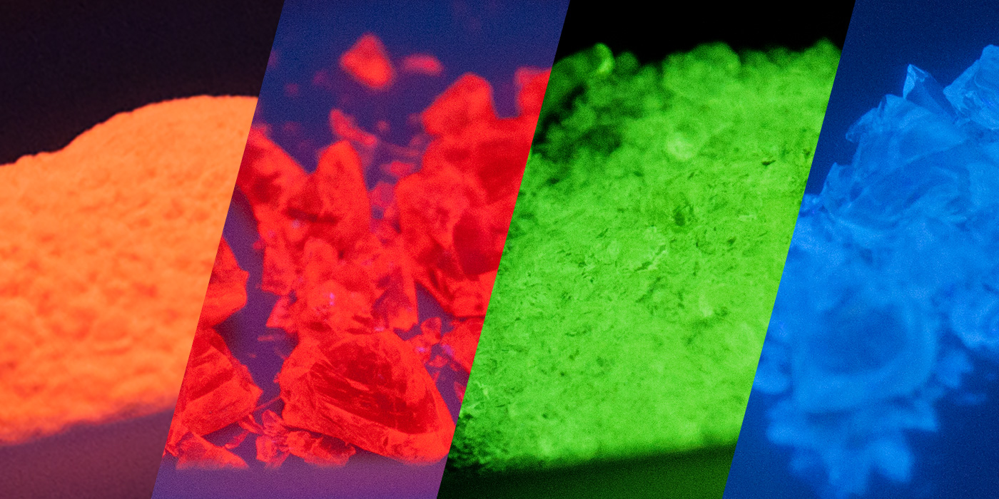
Fluorescent glass examples

What are rare earth elements?

The rare earth elements (REE) are a set of seventeen chemical elements, consisting of the fifteen lanthanides, scandium, and yttrium. Rare earth elements are generally very reactive with oxygen in the ambient atmosphere, and readily form compounds known as rare earth oxides (REO). These oxides are thermally stable, and they are usually the final product when fired in the presence of oxygen. The final stoichiometry is closely dependent upon the temperatures and the oxygen pressure in the ambient atmosphere.

Rare earth elements are called such due to their even distribution over the Earth, making it hard to find a large amount in one location. Scandium and yttrium are included in the REE’s due to their original discovery alongside the lanthanides and also share similar chemical characteristics. REEs are widely distributed geographically, with the key ores mined in India, Brazil, and Malaysia; but they are chiefly mined, concentrated, and separated in China. Semi-fabrication also takes place in China, making it important to world production on several levels.

Applications of rare earth elements

Rare earth elements have been used for a long time in established industries such as catalysts, glassmaking, lighting, and metallurgy, which combined account for 59% of the total worldwide consumption. They are also being used in newer, high-growth areas such as battery alloys, ceramics, and permanent magnets, which account for the other 41%.

Rare earth elements in glass production

Rare earth oxides have been studied for a long time in the field of glass production, specifically how the addition of these compounds may change the properties of the glass. This started in the 1800s when a German scientist named Drossbach patented and manufactured a mixture of rare earth oxides for decolorizing glass. This was the first commercial use of cerium, albeit in a crude form with other rare earth oxides. In 1912, Crookes of England found cerium excellent for ultraviolet absorption without giving color, making it useful for protective eyeglasses.

The most widely used REEs in glass are erbium, ytterbium, and neodymium. Erbium-doped silica fiber is extensively used in optical communication; ytterbium-doped silica fiber is used in engineering materials processing, and neodymium-doped is applied in glass lasers used for inertial confinement fusion. One of the most important uses of REO in glass is the ability to change the fluorescent properties of the glass.

Fluorescent properties from rare earth oxides

Fluorescence in glass has many applications from medical imaging and biomedical research, to testing media, tracing and art glass enamels. Fluorescent glass is unique in that it can appear ordinary under visible light and then can emit vivid colors when excited by certain wavelengths.

Using REOs directly incorporated into the glass matrix during melting allows the fluorescence to persist, where other glass materials that only have a fluorescent coating often fail.

The fluorescence in optical glass, usually silica, is a result of introducing rare earth ions into the structure during manufacturing. When these active ions are directly excited by an incoming energy source, the REE’s electrons are raised to an excited state. The excited state returns to the ground state by emission of light of longer wavelength and lower energy.

This is particularly useful in industrial processes, where inorganic glass microspheres can be inserted into a batch to identify the manufacturer and lot number for many types of products. The microspheres do not interfere with the transport of the product, but when an ultraviolet light is shone on the batch, a particular color of light is produced, allowing precise provenance of the material to be determined. This can be achieved with all sorts of materials including powders, plastics, papers, and liquids.

It may seem that relying on only color for identification may lead to confusion between batch numbers, but the number of parameters that can be altered provides enormous variety in the microspheres. Along with the precise ratio of various REO, other parameters include particle size, particle size distribution, chemical composition, fluorescent properties, color, magnetic properties, and radioactivity.

Producing fluorescent microspheres from glass is also advantageous. Glass microspheres can be doped to varying degrees with REO’s, withstand high temperatures, high stresses, and are chemically inert. They are superior in all of these areas to polymers, allowing them to be used in much lower concentrations in the products.

One potential limitation is the relatively low solubility of REO in silica glass. This can lead to the formation of rare earth clusters, especially if the doping concentration is higher than the equilibrium solubility, and requires special action to suppress the formation of clusters.

Fluorescent glass from Mo-Sci

For keeping track of batches and processes, Mo-Sci offers fluorescent glasses in a variety of colors and excitation and emission wavelengths in sizes ranging from approximately 10 µm to 600 µm. Visit our online store or contact us to discuss your specific requirements.

References

  1. Haxel, Gordon B., et al. Rare Earth Elements—Critical Resources for High Technology. USGS, https://pubs.usgs.gov/fs/2002/fs087-02/fs087-02.pdf. Accessed 17 June 2019.[RDM4]
  2. Wells, Willard H., and Vickie L. Wells. “The Lanthanides, Rare Earth Elements.” Patty’s Toxicology, American Cancer Society, 2012, pp. 817–40. Wiley Online Library, doi:10.1002/0471435139.tox043.pub2.[RDM5]
  3. Elements, R. The Rare-Earth Elements — Vital to Modern Technologies and Lifestyles. (2004) https://pubs.usgs.gov/fs/2014/3078/pdf/fs2014-3078.pdf
  4. Strauss, M. L., & Strauss, M. (n.d.). THE RECOVERY OF RARE EARTH OXIDES FROM WASTE FLUORESCENT LAMPS https://mountainscholar.org/bitstream/handle/11124/170305/Strauss_mines_0052N_11053.pdf?sequence=1 
  5. Jordens, A., Cheng, Y. P., & Waters, K. E. (2013). A review of the beneficiation of rare earth element bearing minerals. Minerals Engineering, 41, 97–114. https://doi.org/10.1016/j.mineng.2012.10.017 
  6. Report, S. I. (2011). Rare Earth Elements — End Use and Recyclability Scientific Investigations Report 2011 – 5094. https://pubs.usgs.gov/sir/2011/5094/ 
  7. Adachi, G., & Imanaka, N. (1998). The Binary Rare Earth Oxides, 2665(94). https://pubs.acs.org/doi/abs/10.1021/cr940055h
  8. Riker, L. W., Optical, S., & Incorporated, G. (1981). The Use of Rare Earths in Glass Compositions, 81–94. https://pubs.acs.org/doi/pdfplus/10.1021/bk-1981-0164.ch004
  9. Vasconcelos, H. C.  and Pinto, A. S. (2017)Fluorescence Properties of Rare-Earth-Doped Sol-Gel Glasses https://www.intechopen.com/books/recent-applications-in-sol-gel-synthesis/fluorescence-properties-of-rare-earth-doped-sol-gel-glasses 
  10. Mo-Sci.com Fluorescent Glass Microspheres https://mo-sci.com/en/products/glass-microspheres/fluorescent-glass-microspheres