Sunday, 8 May 2022

Glass 101: Glass Furnace Types


Glass 101: Glass Furnace Types

Posted  on 


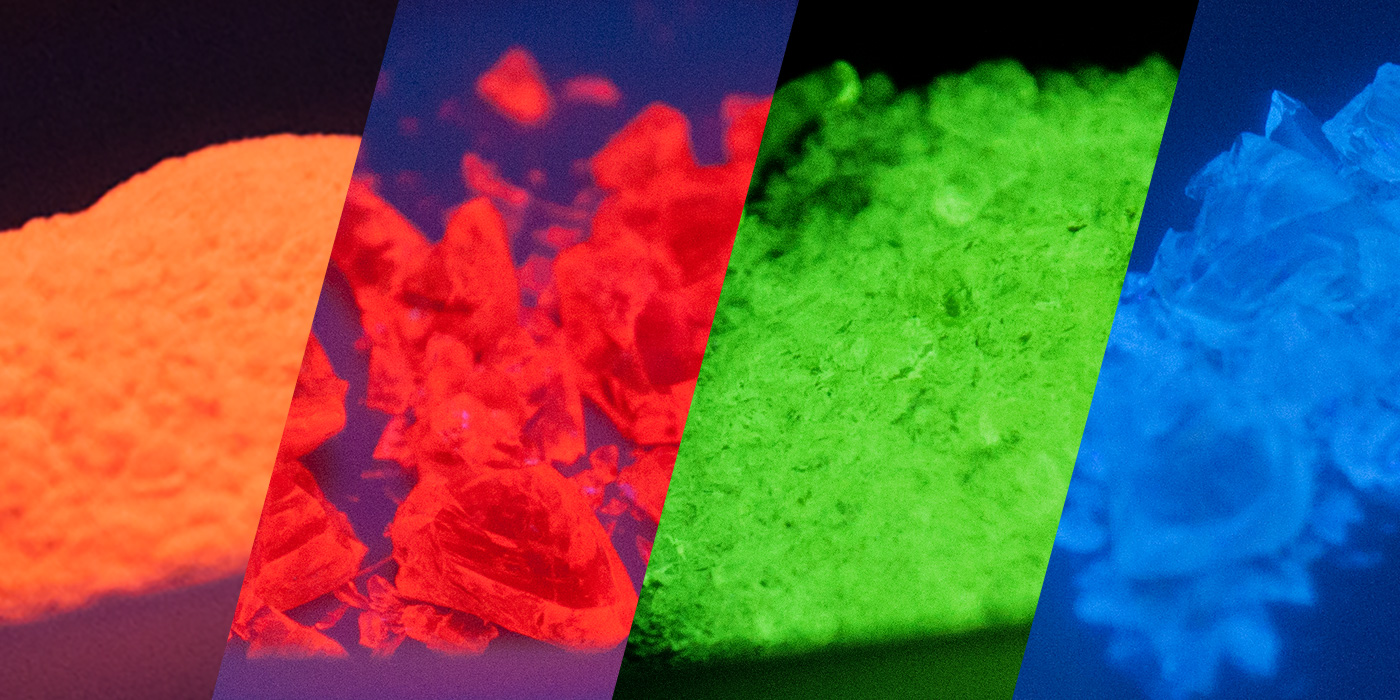
Humans have been making glass for over three thousand years.1 Despite its age, glass is both ubiquitous and cutting-edge, having found tried-and-tested applications in architecture, transportation, and insulation; as well as more novel applications in electronics, biomaterials, and renewable energy.2,3

Much has changed in three thousand years, and as we continue to designate glass to new applications, the technology that we use to produce various types of glass has improved and diversified. At Mo-Sci, for example, we use a variety of glass production methods to produce glasses with varying hardness, thermal shock resistance, electrical conductivity, optical characteristics, and many other properties. In this article we examine some of the most common glass production methods and furnace types and how they’re used to produce glass for different applications.4

Types of glass production processes

Almost all glass is produced in a furnace, where a precise mixture of raw materials is combined and melted into a homogeneous mixture. Like many industrial manufacturing processes, glass melting can be broadly categorized as either a continuous or discontinuous (batch) process.

Continuous glass production

Continuous glass melting processes work like a production line: a mixture of raw ingredients is added continuously at one end of the furnace, and glass is extracted continuously at the other. Continuous melting processes are high-throughput and preferred wherever a high volume (say 100-500 tons per day) of the same type of glass is required. Continuous processing is typically used for production of architectural glass, fiberglass, screens for consumer electronics, and food and beverage containers.

Discontinuous or batch production

In discontinuous or batch processing, a batch of raw materials is added to a single melting vessel and melted into glass. Once the glass is formed, it can be removed from the vessel and formed into products. Batch-processing glass in this manner trades throughput for flexibility, enabling manufacturers to produce multiple formulations of glass depending on customer demand, without cross-contamination.

Discontinuous glass melting is typically used for smaller production runs and is often required for uncommon glass types with relatively niche applications such as optics, electronics or signal applications.

Types of glass furnaces

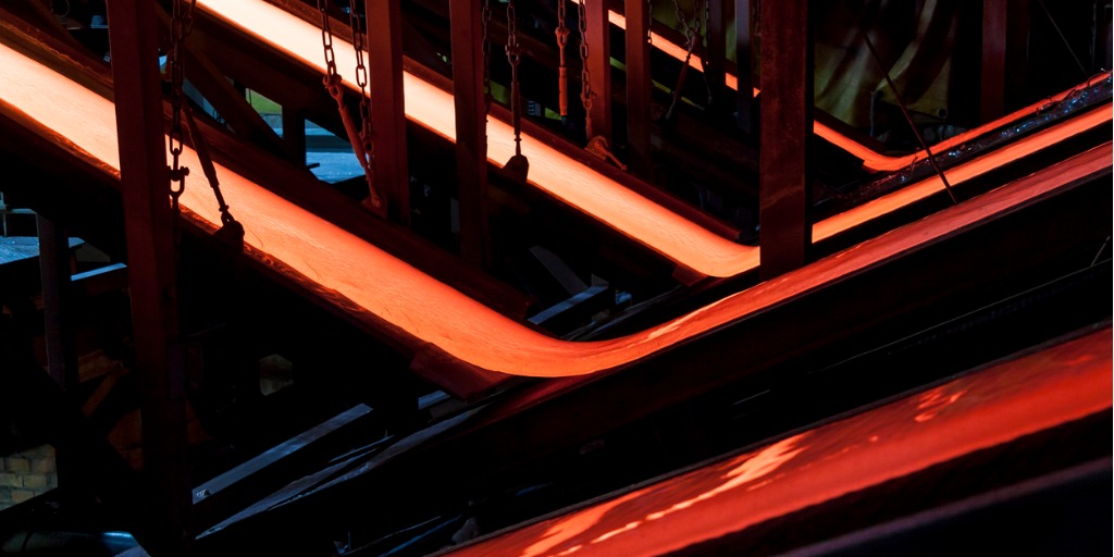
The melting point of most glasses lies around 1,400-1,600°C, depending on its composition. As a result, glass production requires a great deal of heat energy, usually provided in the form of natural gas injected into a combustion chamber. Because of this high energy demand, glass furnaces are constructed to minimize heat loss, and often feature some form of waste-heat reclamation system.

Regenerative glass furnaces

Regenerative furnaces are one such example: these furnaces pipe hot exhaust gas out via a regeneration chamber containing a ‘checkerwork’ of refractory bricks – often referred to simply as ‘checkers’. These bricks have a high resistance to thermal shock as well as high specific heat capacity, and act as a thermal energy store.

Regenerative furnaces run in cycles: the direction of gas flow is periodically reversed so that combustion gas is passed over the now-hot refractory bricks on the way to the combustion chamber, absorbing and making use of the waste thermal heat from the previous half-cycle.

Regenerative furnaces always have an even number of regeneration chambers, so that heat regeneration can occur in both directions. Regenerative glass furnaces can be either cross-fired or end-fired depending on application: cross-firing, the use of multiple combustion gas inlets down opposing sides of the furnace, allows more precise control over the location and temperature of hot spots within the furnace; while end-firing (a single inlet of combustion gas at the end of the chamber) generally reduces structural heat losses due to the increased residence time of the combustion gases.5

Recuperative glass furnaces

Recuperative furnaces employ a slightly different approach to reclaim waste heat. In this type of furnace, the chimney and gas inlets are coupled with a radiative heat exchanger.

This enables the continuous transfer of heat from exhaust gas to combustion gas, without the requirement for gas flow reversal as in regenerative furnaces. This enables recuperative furnaces to be employed for continuous glass melting applications, while also offering a relatively low investment cost.

The absence of regeneration chambers also simplifies construction of the furnace and results in a smaller footprint; however, the heat transfer efficiency of recuperative furnaces is generally lower than that of regenerative furnaces.6

Oxygen-fuelled (“oxy-fuel”) glass furnaces

Oxygen-fuelled (“Oxy-fuel”) glass furnaces are a relatively new way of tackling the problem of high heat energy demand: by replacing the air entering the furnace with oxygen (typically at over 90% purity), the total amount of gas entering the chamber can be reduced while maintaining the same combustion energy input.

This means the energy required to heat the input gas is reduced, while also reducing waste heat in exhaust gas. Other furnaces waste a large amount of energy simply heating the nitrogen in the air.

In general, oxy-fuel furnaces have the same basic design as recuperative furnaces, with multiple lateral burners and a limited number of exhaust ports. Most oxygen-fired glass furnaces don’t use heat recovery systems to pre-heat the oxygen supply to the burnersalthough there are some developments in oxygen and natural gas preheating.

The benefits of oxy-fuel furnaces include cheaper furnace designs, lower NOx emissions per ton of molten glass, smaller flue gas volumes, smaller footprints for furnace systems, and reductions in fuel consumption.7

While oxygen costs may potentially exceed the reduction in fuel costs, research indicates that switching to an oxy-fuel furnace substantially reduces energy costs for both large and small glass manufacturing operations.8

All-electric glass furnaces

Electrically heated furnace technology is nearly as old as regenerative furnace technology.9 These work in a radically different way to conventional furnaces, avoiding combustion altogether and instead imparting heat energy to the glass mixture using high-voltage electrodes. These are typically used for fiberglass production but are also used for specialty glasses.

Typically used for small-batch production, all-electric furnaces offer high thermal efficiency, a high degree of control over temperature, and can yield highly homogeneous glass while minimizing atmospheric pollution and economizing raw materials that volatilize readily.10

References

  1. Glass Timeline – Important Dates and Facts. Available at: http://www.historyofglass.com/glass-history/glass-timeline/. (Accessed: 22nd January 2019)
  2. Bioactive Glass – Mo-Sci Corporation. Available at: https://mo-sci.com/bioactive-glass. (Accessed: 22nd January 2019)
  3. Glass – Mo-Sci Corporation. Available at: https://mo-sci.com/sealing-glass. (Accessed: 22nd January 2019)
  4. Lecture 3: Basics of industrial glass melting furnaces IMI-NFG Course on Processing in Glass. Hubert, M. (2015).
  5. Regenerative Furnaces | Industrial Efficiency Technology Database Available at: http://ietd.iipnetwork.org/content/regenerative-furnaces. (Accessed: 22nd January 2019)
  6. Recuperative Furnaces | Industrial Efficiency Technology Database
    Available at: http://ietd.iipnetwork.org/content/recuperative-furnaces. (Accessed: 17th June 2019)
  7. Oxy-Fuel Furnace | Messer Group
    Available at: https://www.messergroup.com/minerals/glass/oxyfuel-furnace. (Accessed 17 June 2019)
  8. Energy Efficiency Improvement and Cost Saving Opportunities for the Glass Industry An ENERGY STAR® Guide for Energy and Plant Managers. Worrell, E., Galitsky, C., Masanet, E. & Graus, W. (2008).
  9. “The Efficient Future for the Glass Industry Is ‘All-Electric.’” Eurotherm by Schneider Electric, 27 Dec. 2018, https://www.eurotherm.com/en/glass-news/the-efficient-future-for-the-glass-industry-is-all-electric/.
  10. Electric melting of glass. Stanek, J. & Matej, J. J. Non. Cryst. Solids 84, 353–362 (1986).
  11. Glass Products – Mo-Sci Corporation. Available at: https://mo-sci.com/en/products. (Accessed: 22nd January 2019)

Wednesday, 4 May 2022

Uneven slumps

Credit: Lara Duncan


Uneven slumps – where the glass does not slide down the sides evenly, leaving one side higher than the other – are common in moulds with steep sides.  Another common cause is uneven weight on the blank – where there are more layers on one side than another.  Yet another common cause of uneven slumping is the blank having large areas of glass with different viscosities.

Things I can think of to avoid the problem.

While the glass is firing

Use a moderate rate of advance to the target temperature. Once that is reached, peek every 10 minutes to observe how the slump is proceeding.  When the slump begins to go off centre, reach in with protective gear and adjust it back to even.  The kind of protective gear you need is shown in this post.

An alternative to moving the glass is to tip the mould.  If the mould is relatively shallow with a flat bottom,  there is not much you can achieve by this action.  On deeper moulds, you can elevate one side of the mould.  This puts the elevated side closer to the top and so into a hotter part of the kiln.  This means that you elevate the side that is not slumping as quickly.  You do this because the slowly slumping glass needs more heat in relation to the faster slumping side.  It seems counter intuitive, until you realise you are putting the slow side into greater heat.  You will need to continue observing at intervals to know when the glass is slumping evenly. At that point you can return it to level.

I admit that moving the glass is my choice almost all the time.  It works well on moderately deep moulds.  Elevating one side of the mould while firing requires more time in the kiln that I want to give.  Tipping the mould works best on very deep moulds and so I view it as a special case.


Before the slumping begins

Most of the time we make our blanks the same diameter/dimension or slightly larger than the mould. This allows the glass to rest on the rim and be certain it is as level as the rim of the mould is.  However, this also creates an edge which the glass needs to slide over as it slumps.  Especially with steep sided moulds.

A fix for this is to make the blank fit just inside the rim.  Then it does not have to slide over the rim, and avoids the risk of hanging up on one part rather than another.  You will need to ensure the glass is level within the mould as well as the mould itself, in this case.  If you take this approach of internal placing and you want a piece with a particular final dimension, you should buy a mould larger than the final size needed.

You can combine this placing of the glass internally with another preventative for uneven slumps in deep moulds.  You can grind a small bevel on the underside of the edge to help the glass have greater contact with the mould, so resisting uneven movement.  This can be done separately from fitting the glass inside a steep sided mould, but is most likely to be successful if performed on a blank smaller than the mould dimensions.


Uneven slumps in kilnforming can be corrected during the firing or by preparation of the blank in relation to the mould before the firing.

Further information is available in the ebook: Low Temperature Kiln Forming.

Sunday, 1 May 2022

Glass 101: Making Fluorescent Glass with Rare Earth Oxides


Glass 101: Making Fluorescent Glass with Rare Earth Oxides

Posted  on 


Fluorescent glass examples

What are rare earth elements?

The rare earth elements (REE) are a set of seventeen chemical elements, consisting of the fifteen lanthanides, scandium, and yttrium. Rare earth elements are generally very reactive with oxygen in the ambient atmosphere, and readily form compounds known as rare earth oxides (REO). These oxides are thermally stable, and they are usually the final product when fired in the presence of oxygen. The final stoichiometry is closely dependent upon the temperatures and the oxygen pressure in the ambient atmosphere.

Rare earth elements are called such due to their even distribution over the Earth, making it hard to find a large amount in one location. Scandium and yttrium are included in the REE’s due to their original discovery alongside the lanthanides and also share similar chemical characteristics. REEs are widely distributed geographically, with the key ores mined in India, Brazil, and Malaysia; but they are chiefly mined, concentrated, and separated in China. Semi-fabrication also takes place in China, making it important to world production on several levels.

Applications of rare earth elements

Rare earth elements have been used for a long time in established industries such as catalysts, glassmaking, lighting, and metallurgy, which combined account for 59% of the total worldwide consumption. They are also being used in newer, high-growth areas such as battery alloys, ceramics, and permanent magnets, which account for the other 41%.

Rare earth elements in glass production

Rare earth oxides have been studied for a long time in the field of glass production, specifically how the addition of these compounds may change the properties of the glass. This started in the 1800s when a German scientist named Drossbach patented and manufactured a mixture of rare earth oxides for decolorizing glass. This was the first commercial use of cerium, albeit in a crude form with other rare earth oxides. In 1912, Crookes of England found cerium excellent for ultraviolet absorption without giving color, making it useful for protective eyeglasses.

The most widely used REEs in glass are erbium, ytterbium, and neodymium. Erbium-doped silica fiber is extensively used in optical communication; ytterbium-doped silica fiber is used in engineering materials processing, and neodymium-doped is applied in glass lasers used for inertial confinement fusion. One of the most important uses of REO in glass is the ability to change the fluorescent properties of the glass.

Fluorescent properties from rare earth oxides

Fluorescence in glass has many applications from medical imaging and biomedical research, to testing media, tracing and art glass enamels. Fluorescent glass is unique in that it can appear ordinary under visible light and then can emit vivid colors when excited by certain wavelengths.

Using REOs directly incorporated into the glass matrix during melting allows the fluorescence to persist, where other glass materials that only have a fluorescent coating often fail.

The fluorescence in optical glass, usually silica, is a result of introducing rare earth ions into the structure during manufacturing. When these active ions are directly excited by an incoming energy source, the REE’s electrons are raised to an excited state. The excited state returns to the ground state by emission of light of longer wavelength and lower energy.

This is particularly useful in industrial processes, where inorganic glass microspheres can be inserted into a batch to identify the manufacturer and lot number for many types of products. The microspheres do not interfere with the transport of the product, but when an ultraviolet light is shone on the batch, a particular color of light is produced, allowing precise provenance of the material to be determined. This can be achieved with all sorts of materials including powders, plastics, papers, and liquids.

It may seem that relying on only color for identification may lead to confusion between batch numbers, but the number of parameters that can be altered provides enormous variety in the microspheres. Along with the precise ratio of various REO, other parameters include particle size, particle size distribution, chemical composition, fluorescent properties, color, magnetic properties, and radioactivity.

Producing fluorescent microspheres from glass is also advantageous. Glass microspheres can be doped to varying degrees with REO’s, withstand high temperatures, high stresses, and are chemically inert. They are superior in all of these areas to polymers, allowing them to be used in much lower concentrations in the products.

One potential limitation is the relatively low solubility of REO in silica glass. This can lead to the formation of rare earth clusters, especially if the doping concentration is higher than the equilibrium solubility, and requires special action to suppress the formation of clusters.

Fluorescent glass from Mo-Sci

For keeping track of batches and processes, Mo-Sci offers fluorescent glasses in a variety of colors and excitation and emission wavelengths in sizes ranging from approximately 10 µm to 600 µm. Visit our online store or contact us to discuss your specific requirements.

References

  1. Haxel, Gordon B., et al. Rare Earth Elements—Critical Resources for High Technology. USGS, https://pubs.usgs.gov/fs/2002/fs087-02/fs087-02.pdf. Accessed 17 June 2019.[RDM4]
  2. Wells, Willard H., and Vickie L. Wells. “The Lanthanides, Rare Earth Elements.” Patty’s Toxicology, American Cancer Society, 2012, pp. 817–40. Wiley Online Library, doi:10.1002/0471435139.tox043.pub2.[RDM5]
  3. Elements, R. The Rare-Earth Elements — Vital to Modern Technologies and Lifestyles. (2004) https://pubs.usgs.gov/fs/2014/3078/pdf/fs2014-3078.pdf
  4. Strauss, M. L., & Strauss, M. (n.d.). THE RECOVERY OF RARE EARTH OXIDES FROM WASTE FLUORESCENT LAMPS https://mountainscholar.org/bitstream/handle/11124/170305/Strauss_mines_0052N_11053.pdf?sequence=1 
  5. Jordens, A., Cheng, Y. P., & Waters, K. E. (2013). A review of the beneficiation of rare earth element bearing minerals. Minerals Engineering, 41, 97–114. https://doi.org/10.1016/j.mineng.2012.10.017 
  6. Report, S. I. (2011). Rare Earth Elements — End Use and Recyclability Scientific Investigations Report 2011 – 5094. https://pubs.usgs.gov/sir/2011/5094/ 
  7. Adachi, G., & Imanaka, N. (1998). The Binary Rare Earth Oxides, 2665(94). https://pubs.acs.org/doi/abs/10.1021/cr940055h
  8. Riker, L. W., Optical, S., & Incorporated, G. (1981). The Use of Rare Earths in Glass Compositions, 81–94. https://pubs.acs.org/doi/pdfplus/10.1021/bk-1981-0164.ch004
  9. Vasconcelos, H. C.  and Pinto, A. S. (2017)Fluorescence Properties of Rare-Earth-Doped Sol-Gel Glasses https://www.intechopen.com/books/recent-applications-in-sol-gel-synthesis/fluorescence-properties-of-rare-earth-doped-sol-gel-glasses 
  10. Mo-Sci.com Fluorescent Glass Microspheres https://mo-sci.com/en/products/glass-microspheres/fluorescent-glass-microspheres 

Wednesday, 27 April 2022

Displays for Small Tables

Frequently small or busy craft fairs provide a relatively a small space or table to display your glass.  This means you need to make an impact with little area in which to do it.


There is also guidance elsewhere, but these are some basic ideas to get you started thinking about how to use the space you have and make your presentation stand out.

credit: CountryHeartandHome


Make your display like a shop window display

Think about how a shop with small windows works to display things to attract your attention.  Use your stand to display a single theme or style (sometimes called a brand).  Present your key pieces in a complementary but muted background.  Co-ordinate colour, or shape, or function.  Do not put everything out at once.  Give each of your glass pieces space.  Keep extra stock behind or under the table to meet the need for different colours, sizes or shapes.  Give your pieces space to be appreciated individually. The more unity you can give to your display, the more chance you will get the attention your glass deserves.


Be imaginative in your use of display materials

Think about props you have around the studio or in your home that can complement your glass.  Look for things that fit your style of work, or the theme you are presenting.  It is the unusual, but complementary coverings and props that can help you stand out from the other displays.


Height provides interest and space

You might consider a self-supporting stand that can be placed on the table and provide shelves for your glass – as long as they are stable.  You can drape appropriately sized boxes that you brought the stock in to give height to the display.  If the boxes are appropriate, you can use them bare as platforms or shelves, depending on the arrangement.  Always think about ways to build higher, but secure, displays for your glass.  After all glass looks best with light coming through rather than flat on a table.
credit: dizziebhooked.wordpress.com


Make your display fit the glass you make

Think about what is needed to show your glass off to its best.  Mostly this will be vertical with light filtering through.  Vertical light behind or in front of the glass is good.  This is to avoid dazzling the visitor rather than displaying the glass.  It may be that jewellery is best flat, although earrings can be stunning with light behind.  You can consider constructing something that does not need a table.  Look for inspiration at the kinds of displays used by retailers to save space.

credit: pinterest


Create the illusion of space

Use light colours for table coverings and display materials.  It gives a sense of space, that black does not. Using the same colour throughout gives a sense of unity in the display.

Tablecloths are most often used because they are easy to transport, but they are not the only portable material to use.  You could consider rolls of paper, foam board, and other materials to give a clean minimalist base for the display.

What more could be done with that space behind?
credit: MacrameUK


Space behind your stall

Often there is a backing to the stall.  Make use of it if it is there.  You need to determine in advance from the organisers what backing there is to the stall you will be allocated.  If there is a wall or other partition, make sure you leave it as you found it.  You can also think about providing your own stall backing with the organiser’s permission.   Using the back of the stall increases the space you have to display your glass.


There are many ways to utilise small spaces at craft fairs. Your imagination will be the only limit.  Think of shop displays, build up, give your glass space, ensure good lighting, use the back of your space.

Sunday, 24 April 2022

Glass 101: Glass Formers – The Backbone of Glass


Glass 101: Glass Formers – The Backbone of Glass

Posted  on 


Abstract image representing a glass network

Glass is a state of matter that exists separately from the conventional forms of metal, polymers, and ceramics. There is a wide and varied number of applications for glass that each require a different set of properties. Glass properties are controlled by the composition. One of the most fundamental changes that can be made to the composition is the basic unit of the glass: the network former. The former can be thought of as the backbone of the glass, and changing this element or compound will fundamentally change the properties of the final material.

How are formers used in glass production?

Glass formers are added to the bulk material to facilitate the formation of a glass and form the interconnected backbone of the glass network. The first paper to discuss these components was written in 1932 by Zachariasen, which is considered a landmark in glass research.1 In this paper, he outlines his theories on glass and classifies the three types of cation that glass networks are composed of: network formers, network modifiers, and intermediates. 

Some common cations that are in network formers are boron, silicon, germanium, and phosphorus. They have a high valence state (meaning they have a surplus or deficit of electrons allowing them to bond easily with other atoms) and will covalently bond with oxygen. Network ions that alter the glass network and intermediates are added to gain special properties in the glass.

Applications of glass formers

Various glass formers are used in varying ratios with modifiers and intermediates to produce a glass that can withstand the rigors of a specific application. For example, a glass suitable for handling high-temperature liquids will be made of a different composition than one that is being used for decorative purposes. 

Silicate glass

Silicate glass is one of the earliest types of glasses and is still produced worldwide today. It is formed of Si4+ ions that are covalently bonded to four oxygen atoms, to form SiO4 in tetrahedral shapes.2 They then connect to other tetrahedra by bridging oxygen ions. If each of the tetrahedra is joined corner to corner, it forms the SiO2 polymorph cristobalite that has significant long-range order. This long-range order produces a highly connected network which leads to a high softening point, a low diffusion coefficient, and a small coefficient of thermal expansion (CTE).

If the silica is worked at lower temperatures, it possesses only short-range order. Intermediates, such as sodium ions, can then be introduced to the silica glass to form alkali silicate glass. This is done through the addition of Na+ ions, each one of which creates one non-bridging oxygen. This reduces the network connectivity, resulting in decreased viscosity, and an increased diffusion coefficient and CTE. There is also increased ionic conductivity and reduced chemical resistance.

Boron oxide glasses

When boron oxide is used as the former, the glass is known as borate glass. In this case, the structure is composed of corner-sharing BO3 triangles connected by bridging oxygen. Borate glass can also be made into an alkali form through the addition of Na+ ions. 

However, in contrast to silicate alkali glasses, the initial addition of these alkali ions has the inverse effect on borate glasses. It causes an increase in network connectivity, a reduction in the CTE and an enhancement in thermal and chemical resistance.3 Alkali borosilicate glass is also known as Pyrex® glass; the improved physical properties make it useful for lab equipment and piping, as well as the tiled coating on the space shuttle.

Phosphate glass

Phosphate glasses are based on P2O5, with CaO and Na2O as modifiers.4 Initially these glasses were used for industrial applications such as clay processing and pigment manufacturing, but more recently they have been put to more specialised uses. Research has found that the constituent ions of phosphate glass are similar to those present in the organic mineral phase of bone.5 This chemical affinity to bone sees these glasses being developed for biomedical use, as the inert nature of the glass is ideal for deployment within the body.

Mo-Sci glasses

Mo-Sci has extensive experience in developing and manufacturing glass produced from various types of formers.6 We offer a number of standard glass compositions such as soda-lime silicate, barium titanate, and type 1A borosilicate, as well as being able to develop custom glass compositions for specific applications. Contact us for more information.

References

  1. Zachariasen, W. H. The atomic arrangement in glass. J. Am. Chem. Soc. 54, 3841–3851 (1932). https://pubs.acs.org/doi/pdf/10.1021/ja01349a006
  2. Hosford, W. F. & Hosford, W. F. Amorphous Materials. Mater. Sci. 153–167 (2009). https://ocw.mit.edu/courses/materials-science-and-engineering/3-071-amorphous-materials-fall-2015/lecture-notes/MIT3_071F15_Lecture2.pdf
  3. Yuntian Zhu. MSE200 Lecture19(CH.11.6,11.8)Ceramics. 19, 1–21 https://people.engr.ncsu.edu/ytzhu/Class-Teaching/MSE200/Lecture19-Nov23.pdf
  4. Richard K. Brow. Review: the structure of simple phosphate glasses. J. Non. Cryst. Solids 263–264, 1–28 (2000). https://www.sciencedirect.com/science/article/pii/S0022309399006201
  5. Rahaman, M. N. Bioactive ceramics and glasses for tissue engineeringTissue Engineering Using Ceramics and Polymers: Second Edition (2014). https://www.sciencedirect.com/science/article/pii/B978085709712550003X
  6. Mo-Sci Glass Products https://mo-sci.com/en/products

Wednesday, 20 April 2022

Annealing Previously Fired Items

“Double the annealing soak time for each firing” and “Slow the rate of advance each time you fire” are common responses as a diagnosis when a piece breaks in the slumping process.  It may come from the fact that once fired, It is now a single piece that needs a slower rate of advance on the second firing.  I’m not sure where the idea of doubling the annealing process originates.

You need to think about why you would slow the rate of advance and double the anneal for each subsequent firing of the piece.  This is an investigation of the proposals.

Thickness determines ramp rates and annealing

Annealing soak lengths and cooling rates are related to thickness and complexity.  If no additions or complications are added between the previous and the current firing, there is no reason to extend the soak or decrease the rate of cooling.

You of course, need to consider what lay-up and process you are using in the additional firing.  Have you added any complexity to the piece in the previous or the current firing?  If so, you do need to consider how those changes will affect the firing requirements.

Fire polishing

The question to be asked is, “if the piece was properly annealed in the first firing and shows no significant stress, why do I need to change the firing?”

The answer is, “you only need to slow the heat up because it is a single piece now.”  You do need to know that the existing stress is minimal, of course. A note on stress testing is here.  If there is little or no stress from the previous firing, the annealing and cooling can be the same as the previous firing.  Nothing has changed. You are only softening the surface to a shine.  The anneal was adequate on the first firing, and it will be on the second.

If you are firing a pot or screen melt, you have added a complexity into the firing. This is because of the high temperatures used in the first firing.  It means you may wish to be more cautious about a re-firing to eliminate bubbles, or for a fire polish for the surface.

Frit layers

If you are adding confetti or thin layers of frit or powder you have not significantly changed the piece.  You can re-fire the piece as though you are fire polishing any other piece of the same dimensions.


Additional layers

If you are adding more full layers in subsequent firings, you need to reduce the rate of advance to top temperature.  You also need to extend the soak and reduce the cooling rate according to the new thickness of the piece.  This is because the piece is thicker, so the rate of advance needs to be slower, the time required to adequately anneal is longer, and the cooling rate needs to be slower.  All of these changes in scheduling are to accommodate the additional thickness.

Tack fusing additional pieces

If you are tack fusing pieces to the top of an already fired piece, you need to go slower than you would by just adding a full layer.  Tack fusing pieces to an existing piece adds a significant complication to the firing.  Tack fusing requires a firing for thickness between 1.5 and 2.5 times the actual total height of the piece.  The complexity added is the shading of the base glass from the heat radiating from the elements. 

For example, if your piece from the melt is 9mm/0.375", it would have been annealed with a 90 minutes soak. The first cool would be at 69C/127F per hour, and the second at 125C/225F per hour with the cool to room temperature at 415C/750F. If it shows no significant stress, you can fire polish and anneal in the same way as your initial firing.

But


If you tack fuse pieces on top, then you need to treat the piece as though it were between 15mm/0.625" (a little over 1.5 the thickness) and 25mm/1.0" (a little over 2.5 times) thick.  This would require a soak of 3 or 4 hours.  A cooling rate of between 40C/72F and 15C/27F per hour for the first cooling stage is needed. The second stage between will need a rate between 72C/130F and 27C/49F per hour. The final cooling to room temperature will be between 90C/162F and 240C/432F to room temperature.

Conclusion

If you have made no significant changes in thickness or complexity, the second firing can be the same annealing as the first firing. If you have altered the thickness or complexity of the piece, the second firing will need to be slower.

Further information is available in the ebook Low Temperature Kiln Forming.

Sunday, 17 April 2022

Glass 101: Using Glass Modifiers to Change Glass Characteristics


Glass 101: Using Glass Modifiers to Change Glass Characteristics

Posted  on 


Borosilicate glassware used in chemistry labs

Glass modifiers such as lithium oxide, calcium oxide, and zinc oxide can be used to fine-tune the properties of silicate and borate glass to suit a number of niche engineering applications. In this article we take a look at the ways in which common glass modifiers are used to create high-specification glasses for various applications.

Ordinary glass is a unique material. It’s heat-resistant, exhibiting low thermal expansion and excellent thermal shock resistance; chemically durable; exhibits high electrical resistivity; and of course, is highly optically transparent. These properties have made glass an indispensable material in architecture, labware, electronics, and engineering.

Glass can be further transformed into a true wonder-material through the use of glass modifiers. Just like other materials such as steel, the properties of glass can be precisely tuned and augmented through the careful addition of chemical modifiers to suit a huge array of demanding applications.

Glass structure and composition

The constituents of glass can be broadly divided into three categories: network formers, modifiers, and intermediates.1 Network formers form a highly cross-linked network of chemical bonds and constitute the bulk of the glass. Silicon oxide is the most common network-forming constituent of glass, but glasses based on other oxides such as boron and germanium are also commonly produced.

Modifiers are chemicals that can be added to glass in small quantities to further alter the properties of a glass. These include lithium, sodium, potassium, and calcium; which exist as charged single atoms (ions) amongst the cross-linked network formers, reducing the relative number of strong bonds in the glass and lowering the melting point and viscosity. 

Intermediates; which include titanium, aluminum, and zinc; are chemicals that can behave as network-formers or modifiers depending on the glass composition.2 Glasses are naturally highly disordered, and require a carefully tuned balance of network formers, intermediates, and modifiers to prevent the formation of ordered crystallites within the material.

Effects of glass modifiers

As glass generally acts like a solution, the properties of modified glass can be approximately described by additivity relationships: that is, each ingredient contributes to the bulk properties of the glass by an amount roughly proportional to its concentration.3

Glass modifiers interrupt the normal bonding between glass-forming elements and oxygen by loosely bonding with the oxygen atoms. This creates “non-bridging oxygens,” and lowers the relative amount of strong bonding within the glass. As a result, glass modifiers generally have significant effects on glass properties. 

These include a reduction in melting point, surface tension, and viscosity due to weaker overall bonding within the material. These are some of the primary reasons for using glass modifiers – they make glass easier to work with at lower temperatures without affecting transparency.4 Glass modifiers affect the coefficient of thermal expansion, chemical durability, and the refractive index.

Glass modifiers for high-specification applications

Despite a number of common properties, the unique chemical properties of different glass modifiers can have varying effects on the properties of the glass produced. 

Chemical Durability

The use of alkali metals such as sodium and potassium as modifiers generally reduce the chemical durability of glass, whereas alkaline earth metals such as calcium can increase the chemical durability of glass.5

Resistivity

In electronics, the high resistivity and permittivity of glass lend it to applications in resistors and capacitors. The addition of tellurium, germanium or titanium oxides to glasses in low concentrations have been shown to drastically increase resistivity, making them popular as glass modifiers for ultra-high resistance applications such as hearing aids and infrared detectors.6

Glass for labware

Glass with strong chemical durability and resistance to thermal shock is highly valued in labware manufacturing. The addition of zinc oxide to silicate glass can reduce thermal expansion effects, making it especially resistant to thermal shock. Borosilicate glasses, which use borate as well as silicate as a network former, are also especially thermally resistant and chemically durable, making them a popular choice of material for reaction vessels, test tubes, and other labware.

Specialty optical properties

Some glasses are prized for unusual optical characteristics: zinc-modified glass is widely used in photochromic lenses, while silver, gold, and copper can produce photosensitive glass which changes color in response to incident light.4,7

Bioactive glass

Of particular interest to the biomedical community, bioactive glass is a form of modified glass that closely emulates the properties of the mineral portion of living bone. Bioactive glass is highly biocompatible and forms strong chemical bonds with bone. 

This material consists of around 45% silicate with calcium and sodium acting as the primary modifiers. This results in a comparatively soft glass which can be readily machined into implants for use in the repair of bone injuries.8

Mo-Sci leading precision glass technology

Mo-Sci is a world-leader in precision glass technology and produces a range of high-specification glasses for application in healthcare, electronics, and engineering. With expertise including bioactive glass, high refractive index glass, and fluorescent glass; Mo-Sci is able to produce custom solutions for virtually any glass application. Contact us today with your specifications!

References

  1. Karmakar, B., Rademann, K. & Stepanov, A. L. Glass nanocomposites: synthesis, properties, and applications.
  2. Kienzler, B. Radionuclide source term for HLW glass, spent nuclear fuel, and compacted hulls and end pieces (CSD-C waste). (KIT Scientific Publishing, 2012).
  3. Industrial glass | Britannica.com. Available at: https://www.britannica.com/topic/glass-properties-composition-and-industrial-production-234890#ref608298. (Accessed: 17th May 2019)
  4. Phillips, G. C. A Concise Introduction to Ceramics. (Springer Netherlands, 1991). doi:10.1007/978-94-011-6973-8
  5. Hu, J. MIT 3.071 Amorphous Materials 2: Classes of Amorphous Materialshttps://ocw.mit.edu/courses/materials-science-and-engineering/3-071-amorphous-materials-fall-2015/lecture-notes/MIT3_071F15_Lecture2.pdf
  6. Weißmann, R. & Chong, W. Glasses for High-Resistivity Thick-Film Resistors. Adv. Eng. Mater. 2, 359–362 (2000).
  7. Photosensitive glass. (1948). https://patents.google.com/patent/US2515275
  8. Rahaman, M. N. et al. Bioactive glass in tissue engineering. Acta Biomater. 7, 2355–2373 (2011).