Wednesday, 10 January 2024

Identification of Mechanical and Thermal Stress

The Identification of stress is important in investigating the causes of stress. We have well established clues to help us with our glass selection and alteration of our firing schedules. We can get more information about why the cold glass has broken from the scientific literature. The manufacturers of float glass and the installers of large panes investigate thoroughly the causes of breaks in glass that has been installed. 

One article - Breaking It Down, Why Did the Glass Break? by Timothy Bellovary from Vitro Architectural Glass - looks at mechanical and thermal stress and distinguishing between the two.  This post is quoted extracts from that article. [Text in square brackets are interpolations of mine].   Note that all the illustrations are from the article and are copyrighted.

Source: https://vcn.vitroglazings.com/technical-forumdiagnosing-glass-breakage

Identifying the break origin can provide hints about the following:

·         Mode of glass failure—Was it mechanical or thermally induced stress?

·         The stress or tension level at which the breakage occurred.

·         Other contributing factors—were there digs (deep, short scratches) resulting from glass-to-glass or glass-to-metal contact? Did a projectile hit the glass? Is there edge or surface damage?


To find the origin of a break, the first step is to assess its direction by inspecting the fracture lines… in the glass. These rib-shaped marks, distinguished by a wave-like pattern, begin at the break origin and radiate along break branches, and almost always project into the concave face of these lines.


Figure 1
Diagram of Fracture Line Direction


It’s often helpful to make a basic diagram (see Figure 1) of the fracture lines. … The origin of the break can be determined by:

·         Drawing arrows (indicating fracture line direction) pointing into the concave face of break wave markings in the glass edge.

·         Tracing point-to-tail of arrows back to the break origin.


Mechanical Stress

Low-stress tension breaks are experienced most frequently by residential window and IGU manufacturers. The origin of the break is typically at damaged areas of the edge or surfaces near the edge, such as digs, scratches or chips. In many cases, breakage from damaged glass occurs after the initial edge damage is incurred, such as during IGU fabrication, sashing operations, transportation, job-site handling or storage, or the installation process.

In Figure 2, the break origin is not 90 degrees to the edge of the glass, indicating a tension break caused by bending. Low-stress, mechanical tension breaks often occur from bending at less than 1,500 psi.

Figure 2

Low-Stress Mechanical Tension Break


High-stress tension breaks share one characteristic with low-stress tension breaks: The break origin is not 90 degrees to the edge of the glass, suggesting a tension break caused by bending. However, additional branching of the crack within two inches of the break origin (see Figure 3) indicates that the stress at breakage was likely higher than 1,500 psi.


Figure 3

High-Stress Mechanical Tension Break


Thermal Stress

Thermal stress breaks often originate at the edge of the glass and form virtually 90-degree angles to the edge and surface of the glass.

As with mechanical stress, there are two types of thermal stress breaks: low stress and high stress.


Figure 4

Low-Stress Thermal Break

Low-stress thermal breaks are often indicated by a single break line starting at the break origin point at or near the glass edge and propagating two inches or more before branching into more break lines (see Figure 4). Damaged glass edges are the most frequent cause of low-stress thermal breakage.


High-stress thermal breaks appear as a single break line starting at the break origin point at or near the glass edge and generally branching into additional breaks within two inches [50mm] of the origin. This indicates a breakage brought on by conditions that cause high thermal stress, such as severe outdoor shading on parts of the glazing; heating registers located between the glass and indoor shading devices; closed, light-colored drapes located close to the glass; or glazing in massive concrete, stone or similar framing.


Figure 5

High-Stress Thermal Break

Analysing the Break Origin

A reliable method for estimating the stress level of a break at failure is a mirror radius measurement. Radius dimensions are determined by crack propagation velocity characteristics.

A crack propagates itself through glass with increasing velocity as it moves further from the point of origin. If an object has sufficient energy to propagate a crack through the thickness of the glass, then a “spider web” pattern will form. ….

Near the point of origin, a smooth, mirror-like appearance on the fracture face indicates a low crack velocity. However, as velocity increases (due to higher tension stress), the fracture face takes on a frosted look; then, at the highest velocity, it assumes a ragged or hackled appearance. Mirror radii appear in various forms, depending on the stress level of the fracture.

Figure 6 shows break origins resulting from high tensile stresses, such as bending or thermal stress breaks.

Figure 6

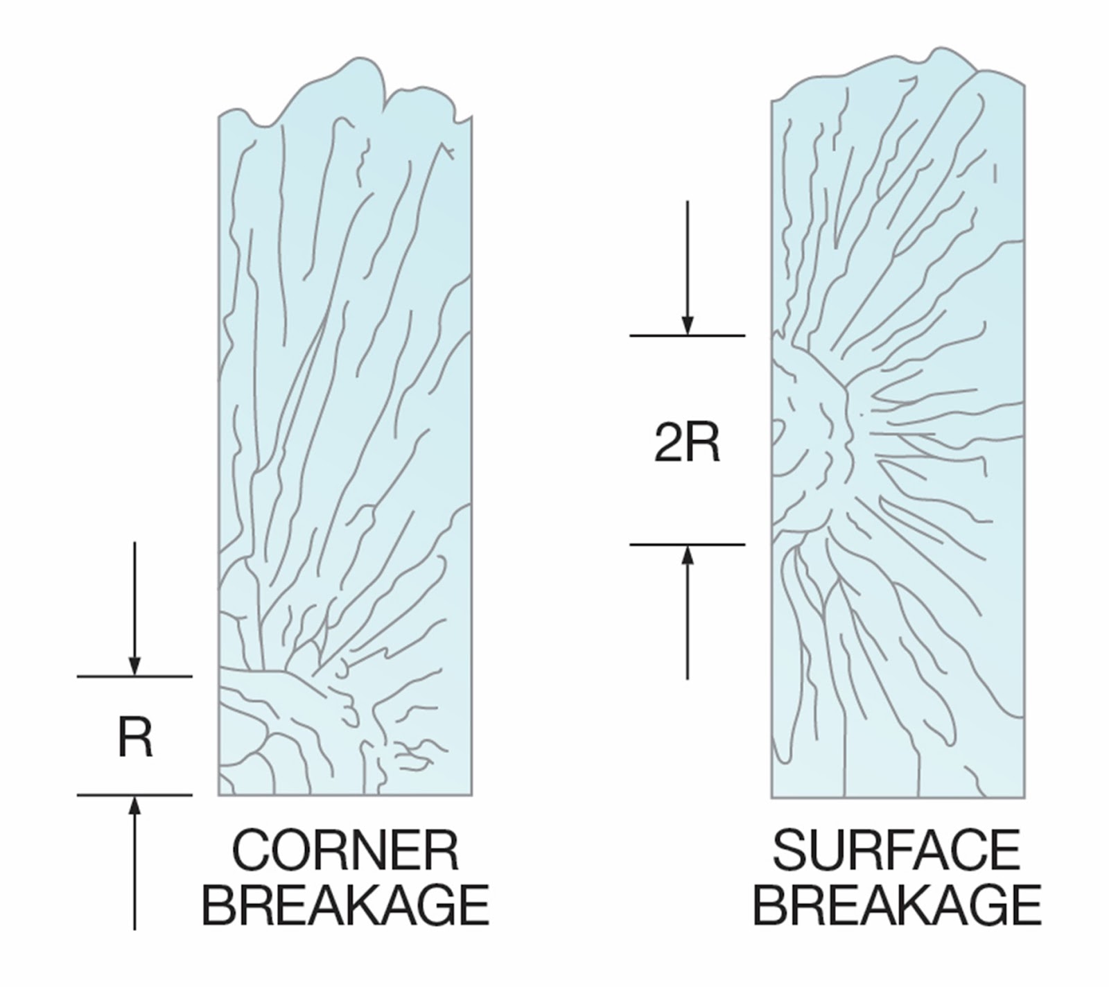
High-Stress Mirror Radii
(R = Mirror radii)


Figure 7 represents the break origins of glass fracturing at low bending stresses. In this example, a smooth fracture face forms across the thickness of the substrate. When the breaking stress is low, the mirror radius is often radial and may extend deeply into the substrate.

Figure 7

Low-Stress Mirror Radii
(R = Mirror radii)


To identify what damaged the glass in the first place, four factors are examined during this analysis:

·         Impact

·         Inclusions

·         Thermal variance

·         Pressure differentials

Impact

Identifying the nature of the breakage pattern can determine whether a foreign object hit the glass and whether the impact was perpendicular or parallel.

Depending on the severity of the impact, the immediate area surrounding the break origin might be cracked, crushed or missing.

                 
Figure 9

High-Stress Mechanical Breakage

[This pattern of break is often exhibited when the separator fails or is insufficient to keep the glass from sticking to the ceramic support shelf.] …

Inclusions

Any undesirable material embedded in glass is considered an inclusion. ... [In general, kilnformers place inclusions within the glass and know the risks of breaks].

Thermal Variance

[This article relates to float glass installations, but the principle remains.] If the temperature difference across a [piece] of glass is great enough, the accompanying stresses can reach levels that cause breakage. … The combination of contact, surface damage and localized temperature gradients can greatly increase the likelihood of breakage.

Pressure Differentials

[This section applies mainly to Insulated Glazing Units. It points out that differences in altitude between the manufacturing and installation sites – in combination with temperature – can cause breaks. It is not of primary importance to most kilnforming, but something which should be considered when installing kilnformed glass in an IGU]

Conclusion

[Occasionally] glass breaks for no obvious reason. Whether it’s a one-off or part of a continuing pattern of incidents, glass breakage is inconvenient, potentially dangerous and costly. … Conducting “post-mortems” on glass breaks helps investigators identify the general reasons for each incident, including the type of failure that caused the break, and the potential original source of the damage. By using the techniques outlined in this article, [kilnformers] may be able to accurately identify the likely origin of such failures and … use that information to prevent future occurrences.

https://vcn.vitroglazings.com/technical-forumdiagnosing-glass-breakage

[An important element in identifying breaks in kilnforming that this article demonstrates is the difference in the angle of the break. A 90 degree angle to the surface indicates a thermal cause to the break. The more branching of the lines of breakage, the greater the stress. The branching breaks indicate there was significant temperature difference.

The breaks which are less than a right angle to the surface indicate a mechanical origin of the stress. This is usually the glass breaking at a weak point when subject to a bending stress.

If the point of origin of the stress can be identified as demonstrated in the article, it may help in determining causes. One of these causes might be hot or cold spots in the kiln.]


Wednesday, 3 January 2024

Stainless Steel Stringer Pots

Credit: Paul Gardner httpswww.facebook.com


 It is a consideration in stringer and murrini work that the pot be re-usable. This has led to the development of stainless steel square pots.  The thorough cleaning of these is difficult even with a lot of banging. Containers with removal bases have been developed as a result.

 The importance of a container with an integrated bottom is to ensure the glass is contained within the pot. To be reusable, the pot can be lined with fibre on sides and bottom. However, fibres can be drawn from the lining into the stream of glass.

Credit: Paul Gardner

 If you have a stainless-steel square with a removable bottom, the pot can be cleaned more easily and does not need the fibre lining. It also allows easy switching of bases with different hole sizes and shapes.

 However, some people have had the difficulty of the glass flowing out between the sides and bottom of the pot and onto the floor of the kiln. Glass is heavy and can float the much lighter stainless steel off the base, allowing the glass to flow sideways as well as through the hole in the base.

 This indicates that the stainless steel square should be weighted down. Placing kiln furniture on top of the pot can avoid it being floated off the base piece. These can be dams made from kiln shelves, dense fire brick, a small shelf, ceramic tiles, or other kiln furniture. Putting the furniture on two opposing corners will be enough to counteract the floating of the pot and still allow radiant heat to reach the glass.

Pots can be made from refractory materials too, such as vermiculite.

Liners for pots

Wednesday, 27 December 2023

Scheduling with the Bullseye Annealing Chart

This post is about adapting the Bullseye chart Annealing Thick Slabs to write a schedule for any soda lime glass as used in kilnforming.

I frequently recommend that people should use the Bullseye chart for Annealing Thick Slabs in Celsius  and Fahrenheit.  This chart applies to glass from 6mm to 200mm (0.25” to 8”).

“Why should the Bullseye annealing chart be used instead of some other source?  I don’t use Bullseye.”

My answer is that the information in the chart is the most thoroughly researched set of tables for fusing compatible glass that is currently available.  This means that the soak times and rates for the thicknesses can be relied upon.

“How can it be used for glass other than Bullseye?”  

The rates and times given in the chart work for any soda lime glass, even float. It is only some of the temperatures that need to be changed.

"How do I do that?"  

My usual response is: substitute the annealing temperature for your glass into the one given in the Bullseye table.

 "It’s only half a schedule."

That is so.  The heating of glass is so dependent on layup, size, style, process, and purpose of the piece.  This makes it exceedingly difficult to suggest a generally applicable firing schedule.  People find this out after using already set schedules for a while. What works for one layup does not for another.

Devising a Schedule for the Heat Up

There is no recommendation from the chart on heat up.  You have to write your own schedule for the first ramps.  I can give some general advice on some of the things you need to be aware of while composing your schedule.

The essential element to note is that the Bullseye chart is based on evenly thick pieces of glass.  Tack fusing different thicknesses of glass across the piece, requires more caution. The practical process is to fire as for thicker pieces.  The amount of additional thickness is determined by the profile being used.  The calculation for addition depends on the final profile.  The calculation for thickness is as follows:

  • Contour fusing - multiply the thickest part by 1.5. 
  • Tack fusing - multiply the thickest part by 2. 
  • Sharp tack or sinter - multiply the thickest part by 2.5.

The end cooling rate for the appropriate thickness is a guide for the first ramp rate of your schedule.  For example, the final rate for an evenly thick piece 19mm/0.75” is 150ºC/270ºF.  This could be used as the rate for the first ramp. 

Bob Leatherbarrow has noted that most breaks occur below 260ºC/500ºF.  If there are multiple concerns, more caution can be used for the starting ramp rate.  My testing shows that using a rate of two thirds the final rate of cooling with a 20 minute soak is cautious.  In this example of a 19mm piece it would be 100ºC/180ºF per hour.

Even though for thinner pieces the rates given are much faster, be careful.  It is not advisable to raise the temperature faster than 330ºC/600ºF per hour to care for both the glass and the kiln shelf.

Once the soak at 260ºC//500ºF is finished, the ramp to the bubble squeeze should maintain the previous rate.  It should not be speeded up.  The glass is still in the brittle phase.

After the bubble squeeze you can use a ramp rate to the top temperature of up to 330C/600F.   AFAP rates to top temperature are not advisable.  It is difficult to maintain control of the overshoots in temperature that are created by rapid rates.  

The top temperature should be such as to achieve the result in 10 minutes to avoid problems that can occur with extended soaks at top temperature.

In the example of an evenly thick 19mm/0.75” piece a heat up full fuse schedule like this could be used:

  • 150ºC/270ºF to 566ºC/1052ºF for 0 minutes
  • 50C/90F to 643C/1191F for 30 minutes
  • 333ºC/600ºF to 804ºC/1479ºF for 10 minutes


If a more cautious approach to the heat up is desired, this might be the kind of schedule used:


  • 100ºC/180ºF to 260ºC/500ºF for 20 minutes
  • 100ºC/180ºF to 566ºC/1052ºF for 0 minutes
  • 50C/90F to 643ºC/1191ºF for 30 minutes
  • 333ºC/600ºF to 804ºC/1479ºF for 10 minutes

This approach is applicable to all fusing glasses.


Adapting the Bullseye Annealing Chart

After writing the first part of the schedule, you can continue to apply the annealing information from the Bullseye chart.  The first part of the anneal cooling starts with dropping the temperature as fast as possible to the annealing temperature.

The method for making the chart applicable to the annealing is a matter of substitution of the temperature.  All the other temperatures and rates apply to all fusing glasses.

Use the annealing temperature from your source as the target annealing  temperature in place of the Bullseye one.  The annealing soak times are important to equalise the temperature within the glass to an acceptable level (ΔT=5ºC).  The annealing soak time is related to the calculated thickness of the piece.  This measurement is done in the same way as devising the appropriate rate for heat up. 

Applying the Cooing Rates

Then apply the rates and temperatures as given in the chart.  The three stage cooling is important.  The gradually increasing rates keep the temperature differentials within acceptable bounds with the most rapid and safe rates.

The temperatures and rates remain the same for all soda lime glasses – the range of glass currently used in fusing, including float glass.  The soak time for the calculated thickness of your glass piece will be the same as in the Bullseye chart.  

This means that the first cooling stage will be to 427ºC/800ºF.  The second stage will be from 427ºC/800ºF to 371ºC/700˚F.  And the final stage will be from 371ºC/700˚F to room temperature.

I will repeat, because it is so important, that the thickness to be used for the anneal soak and cooling rates for your schedule relates to the profile you desire.  A fuse with even thickness across the whole piece can use the times, temperatures, and rates as given in the chart as adapted for your glass.  The thicknesses to use are for:

Contour fusing - multiply the thickest part by 1.5. 

Tack fusing - multiply the thickest part by 2. 

Sharp tack or sinter - multiply the thickest part by 2.5.

An annealing cool schedule for 19mm/0.75" Oceanside glass is like this:

  • AFAP to 510˚C/ 951˚F for 3:00 hours
  • 25˚C/45˚F to 427˚C/800˚F for 0 time
  • 45˚C/81˚F to 371˚C/700˚F for 0 time
  • 150˚C/270˚F to room temperature, off.


Many will wish to turn off the kiln as early as possible.  This is not part of best kilnforming practice.  If you still wish to do this, the turn off temperature must be related to the thickness and nature of the piece.  To turn off safely, you need to know the cooling characteristics of your kiln.  This can be determined by observing the temperature against time and then calculating the kiln’s natural cooling rateAnd then applying that information to cooling the kiln.


The best source for devising schedules is the Bullseye chart for Annealing Thick Slabs.  It is well researched and is applicable with little work to develop appropriate schedules for all the fusing glasses currently in use.


Wednesday, 20 December 2023

Anneal and Cool Relationship

Annealing and cooling are directly related. You cannot extend the anneal soak without also slowing the cooling rates and expect to have a sound piece. What I am seeing on the internet groups about annealing breaks is comments saying the anneal soak is not long enough. So, people add time to the hold at the annealing temperature and still get breaks. They get breaks because the cooling rates are not slowed when the annealing soak time is extended.

A recording of an anneal soak and cool


If you need 3 hours anneal soak, you cannot cool at a rate of 83C°/150°F to 371C°/700°F. An anneal of 3 hours implies you are firing a piece of effectively* 19mm/0.75”. This needs a cool rate of :

  • ·        25°C to 427°C. (45°F/hr to 800°F),
  • ·        45°C/hour to 371°C (81°F/hr to 700°F),
  • ·        150°C/hour (270°F) to room temperature.

Put the other way around, if you can use a first cool rate of 55°C (100°F)/hr you can use a two-hour soak at anneal. That means that you are firing a piece effectively* 12mm/0.5” thick.

But you cannot expect to maintain the required small temperature differential of 5°C/10°F (achieved at the anneal) with a single cool rate. Tests by Bullseye and confirmed by my own recorded tests show that a three-stage cooling is necessary to maintain that small difference of temperature throughout the cooling without using excessive firing times.

A two-hour soak requires cooling in three stages of:

  • ·        55°C /100°F to 427°C/ 800°F
  • ·        99°C/179°F to 371°C/700°F
  • ·        330°C/595°F to room temperature.

If that small 5°C/10°F temperature differential is not maintained in the first stage cooling, temporary stresses can be induced.  Slightly higher levels of temperature differentials can be withstood during the next stages. The stresses induced by larger temperature differences can be great enough to break the glass. In many schedules published online by kilnformers, very long soaks are being used in relation the effective* thickness. But the cool soaks are too rapid in relation to the anneal hold to avoid inducing excessive (although temporary) stress.

This practice presumes the anneal soak is all there is to the production of a sound piece of glass. It is not. The cool rates from annealing to room temperature are important. To repeat, a long annealing soak with fast cool rates can lead to breaks - breaks that are not related to the annealing time. The cooling rates must be related to the amount of time needed for the anneal soak. A fast cool can induce temporary stresses that are great enough to break the glass. The appearance of the break will often be similar to an anneal break.

Don’t worry about using additional electricity with the slower rates of cooling. If the kiln cools more slowly than the scheduled rate, no power will be used. The relays will not have to operate.

Annealing times and cool rates are intimately related. And must be scheduled in relation to one another to avoid unnecessary breaks.

A more extensive discussion of this issue can be found in the ebook Low Temperature Kilnforming.


*”Effectively” in this context means a flat piece of the given dimension. The “thickness” of piece that is of uneven levels - as for a tack fuse - can be calculated to need firing as though it was a multiple of the actual total thickness. The multiple is based on the tack fusing profile.

Wednesday, 13 December 2023

Fold Moulds


These moulds are available in stainless steel forms in various sizes

You can create your own mould for self-supporting display items. Fibre board and vermiculite board are suitable.


I chose 25mm/1” fibre board because I had a suitable piece lying around. It is possible to use thinner fibre board, but the thicker board is more likely to resist deformation over a long use period. The 15mm/0.675” board is suitable for light use. These do not need to be rigidised unless you desire to for a more robust structure. They do not need to be kiln washed unless you feel a better surface will be achieved.

Angled Surface

The 25mm/1” vermiculite board is more durable. It does need to be kiln washed to avoid glass sticking to it. Otherwise’ it is treated just the same as the fibre board.

The width and length of the board are determined by the width and length of the piece you are currently making or envisage making. You can make it longer than current needs and use a stop of a piece of fibre board or other kiln furniture to ensure the glass does not slip down the slope. This allows you to adjust the mould to different lengths for a variety of projects.

Both materials need to have an angle cut from one end. This is the end that will be elevated. It allows the glass to bend directly from the end of the angled board. This angle does not need to be more than 30 degrees from vertical, as most self-supporting items have angles of about 15 degrees or less.

Support

Then a support piece needs to be made. If it is not of fibre board, it needs to be kiln washed to prevent the glass from sticking. This support needs to be as wide as the angled board. The height of support will determine the angle of the finished piece.

It needs to be aligned vertically and directly under the top of the angled board. A try square can help with this alignment. This support also stops the draping glass from curving under the top. It would be interesting for a rocking horse kind of item, but not for a stable decoration.

The support under the elevated end can be made to various heights to obtain various angles on the piece. Also, different heights of support will be required to maintain the same angle on different lengths of the standing piece. This makes the home-made mould much more versatile than the steel ones.

The Stop

The stop is a piece of kiln furniture placed on the slope at the end of the glass to ensure the glass does not slip down during the firing. It is not fixed to the sloped board so that it can be repositioned. If you are using fibre board for the slope and the stop, you can pin the stop to the sloped board. Or you can use heavier kiln furniture, propped as appropriate to form the stop.


Firing notes

Glass lengths

The length of base in relation to upright needs to be determined before firing. You can, of course, cut the excess base length off after firing. I make the base to be the same length as the top leans back. This ensures the piece will not become top heavy.

A spirit level can be used to determine how long the support needs to be. You already know how long the sloped piece of glass is. Place the stop at that distance from the top end of the sloped board. Use a spirit level to indicate the length the base will need to be. When levelled, make a mark on the support. Then measure the distance from the mark to the top of the slope. That length plus the length of the sloped glass will equal the total length of the flat glass.

Scheduling

Use a moderate ramp rate for the thickness of the glass. The top temperature should be about 650˚C/1200˚F. Set the soak time for an hour. Peek frequently from the start of the hold to be sure the glass has draped vertically. When it has advance to the next segment and proceed to anneal.


Sunday, 10 December 2023

Sealing MEMS Devices with Glass


Krista Grayson

However, the success of MEMS devices often hinges on maintaining a hermetic environment to protect their delicate internal components. This is where glass frit sealing technology comes into play, providing a superior solution for achieving reliable hermetic seals in precise applications like MEMS manufacturing and packaging.2

Understanding Hermetic Sealing and its Importance

Hermetic sealing involves creating an airtight barrier around a device to prevent the entry of contaminants, moisture, and other external elements. This sealing technique is crucial for MEMS devices as even minute environmental influences can alter their performance or lead to premature failure. In applications where stability, precision, and reliability are paramount, such as in the aerospace, medical, and telecommunications industries, achieving a hermetic seal is essential.2

Glass Frit Sealing: The Ideal Solution for MEMS

Among the various methods available to achieve hermetic seals, glass frit sealing stands out as a versatile and high-yield approach, particularly suited for MEMS applications. This technique leverages the unique properties of glass to create a reliable, robust, and precise encapsulation for MEMS devices while imposing minimal stress on the bonding surface. In a three-step process, a glass paste is screen-printed on a capping wafer, which is then bonded to the subject device through thermocompression for 10 minutes. During this process, 1000 mBar of force and 440 °C are applied to the material under a vacuum. Capable of bonding both hydrophobic and hydrophilic surfaces, this technique can be applied to almost all commonly used microsystem surface materials, such as aluminum, silicon, and glass.3,4

Tailoring Precision Using the Coefficient of Thermal Expansion (CTE)

As the name implies, glass frit sealing makes use of glass particles, known as frit, which can be precisely formulated to match the coefficient of thermal expansion (CTE) of different materials.4 The CTE of a material refers to how its dimensions change with temperature fluctuations. By tailoring the glass frit’s composition, its CTE can be adjusted to closely match that of the MEMS device and the encapsulating material. This compatibility ensures that, when subjected to temperature variations, the seal remains intact without compromising the structural integrity of the device.2

Mo-Sci, a pioneering glass technology company, has been at the forefront of developing and perfecting glass frit sealing solutions for various high-tech applications, including MEMS devices. Its expertise lies in creating sealing glasses with customizable thermal expansion coefficients. With a diverse range of glass-metal and glass-ceramic seals that are meticulously matched in terms of CTE and are capable of enduring temperatures as high as 1600°C, Mo-Sci is an ideal partner for MEMS manufacturers seeking reliable hermetic sealing solutions.2,5

The Versatility of Glass Frit Sealing

The applications of glass frit sealing extend beyond MEMS devices and encompass a range of cutting-edge technologies:

1. Solar Cells

Sealing glasses find utility in encapsulating perovskite photovoltaic elements. These elements are promising alternatives to traditional silicon solar cells due to their high efficiency and lower production costs. However, perovskite cells are highly sensitive to moisture, whereby even small amounts can completely prevent function. Laser-assisted bonding of glass frit sealing guarantees a durable hermetic barrier, shielding perovskite cells from moisture exposure and locking in lead-containing chemicals.2

2. Metal Ion and Thermal Batteries

In the evolving landscape of energy storage solutions, glass frit sealing plays a pivotal role in enhancing the reliability and longevity of metal ion batteries, including lithium-ion and sodium-ion batteries. These batteries require seals that can withstand high temperatures and resist chemical corrosion. Sealing glasses provide a resilient barrier that enables the efficient operation of these advanced battery technologies.

Sealing glass is also a viable solution for molten salt batteries. These batteries are highly dependent on sodium salts, including sodium-nickel and sodium-sulfur chloride, to achieve remarkable energy and power densities. For this reason, they are an appealing option for large-scale industrial and energy storage applications.

Sealing glasses are classed as a high-energy alternative to conventional polymeric or metal seals as they exhibit excellent resilience against demanding chemical environments but also against the rigorous operating temperatures inherent to molten salt batteries, which can range from 300 °C to 350 °C.2

3. High Temperature Sensors

Glass frit sealing also finds applications in high-temperature environments, such as automotive systems and chemical processing plants. The predictable thermal expansion and corrosion-resistant nature of sealing glass ensure the longevity and stability of sensors operating in extreme conditions.2

4. Solid Oxide Fuel Cells (SOFCs)

SOFCs hold tremendous promise for clean and efficient power generation, but their high operating temperatures present engineering challenges. To create high-temperature sealant materials for SOFCs, Mo-Sci currently utilizes two methods. One relies on a traditional glass-ceramic seal, wherein the glass undergoes crystallization to establish bonds with the sealing components.

The second approach involves the development of viscous-compliant glass seals. These seals remain vitreous throughout application and can self-heal, mitigating the risks associated with thermal stresses and ensuring the long-term stability of SOFCs.This groundbreaking technology is anticipated to play a pivotal role in facilitating the commercialization of SOFCs and driving their widespread adoption.2,6

Embracing the Future with Glass Frit Sealing

Glass frit sealing technology has emerged as a transformative solution for achieving hermetic seals in MEMS devices and a wide array of other advanced applications. By precisely engineering the properties of sealing glasses, companies like Mo-Sci enable manufacturers to create highly reliable and robust encapsulation systems.

As industries continue to push the boundaries of technological innovation, the role of glass frit sealing in safeguarding sensitive components and ensuring optimal device performance becomes increasingly vital.

References and Further Reading

  1. Forbes. Why Timing Must Be Tough Enough For Our Digital World. Available at: https://www.forbes.com/sites/forbestechcouncil/2021/09/02/why-timing-must-be-tough-enough-for-our-digital-world/ (Accessed on 10 August 2023).
  2. Mo-Sci. Sealing Glass Applications. Available at: https://mo-sci.com/sealing-glass-applications/ (Accessed on 10 August 2023).
  3. Chang H-D, et al. (2010). High hermetic performance of glass frit for MEMS package. 2010 5th International Microsystems Packaging Assembly and Circuits Technology Conference. https://doi.org/10.1109/IMPACT.2010.5699539
  4. Knechtel R. (2015). Chapter 31 – Glass Frit Bonding. Handbook of Silicon Based MEMS Materials and Technologies (Second Edition). https://doi.org/10.1016/B978-0-323-29965-7.00031-2
  5. Mo-Sci. Matching Coefficient of Thermal Expansion in Glass Seals. Available at: https://mo-sci.com/matching-cte-in-glass-seals/ (Accessed 10 August 2023).
  6. Mo-Sci. Sealing Glass. Available at: https://mo-sci.com/products/sealing-glass/ (Accessed on 10 August 2023).

source:https://mo-sci.com/sealing-mems-devices-with-glass/?utm_source=Mo-Sci+Newsletter&utm_campaign=b5090c88ed-EMAIL_CAMPAIGN_2023_09_28_06_45_COPY_01&utm_medium=email&utm_term=0_-cf8dcfb60f-%5BLIST_EMAIL_ID%5D&mc_cid=b5090c88ed&mc_eid=0ab94327fb

Wednesday, 6 December 2023

Dog Boning During Slumping

Does the size of the rim affect the amount of dog boning when slumping rectangular items?

This question was prompted by previous testing on the amount of distortion by adding additional elements. I found that single layer pieces stacked 15mm/0.6” or more from the edge do not affect its shape.

This led me to think: “how wide a rim would be required to avoid dog boning of rectangular pieces while slumping?” The premise was that there must be some relation to the width of the rim and the amount of dog boning.


Method

The method I chose was to make two vermiculite moulds. One with an almost square aperture and the other with a rectangular one. These were not large pieces. 

  • One was 27cm by 22cm/ 10.6” by 8.66” with an opening of 10cm by 10.5cm/4” by 4.12”. 
  • The other was 25cm by 22cm/9.84” by 25cm/8.66” with an opening of 19.5cm by 13cm/7.68” by 5.1”. 
  • Both had a drop of 25mm/1”.

The sizes of the rim were proportional to the opening of the mould. The remainder of the mould was merely a support to the rim.

The firing schedule for all pieces was kept the same.

  • Ramp 1   220˚C/396˚F to 677˚C/1252˚F     hold for 1.75 hrs
  • Ramp 2   Full to 482˚C/900˚F                     hold for 1.0 hours
  • Ramp 3   83˚C/150˚F to 427˚C/800˚F         Hold for 0 hours
  • Ramp 4   150˚C/270˚F to 371˚C/700˚F        Hold for 0 hours
  • Ramp 5   300˚C/540˚F to 50˚C/122˚F         Off

Results for single layer slumping

Various widths of single layer rim were tested from 1cm/0.4” to 3cm/1.18” at 2.5cm/1” deep. The 2cm/0.79” rim was also tested at 3cm/1.18” and 3.8cm/1.5” deep.

Square openings

The results showed there is no further reduction in dog boning with rims greater than 2cm/0.79” for square apertures of this size. The dog boning of a 1cm/0.4” rim was 1.5mm/0.6”. The amount of deflection from straight was 0.5mm/0.02” for both 2cm/.079” and 3cm/1.18” rims.

There was no effect of increasing the depth of the slump to 3.8cm/1.5” on a 2cm/0.79” rim.

Rectangular openings

The results were different for slumps into rectangular apertures. The glass on the long side of the opening had greater dog boning at all rim widths from 1.25cm/0.5” to 3cm/1.18” than the shorter side.

  • ·   A 1.25cm/0.5” rim deformed 3mm/1.18” on the long side and 2.5mm/0.98” on the short one.
  • ·   With a 2.5cm/1.0” rim the deformation on the long side was 2.5mm/0.98”. The short side of the opening was 1.5mm/0.6”.
  • ·   A rim of 3cm/1.5” deformed 1mm/0.02” on the long side. The short side of the opening deformed 0.5mm/0.02”.

Results for Two Layer Slumping

The big surprise for me was the greater amount of dog boning on the slumping of two layers. I expected less.

The two-layer slumping was done on the same moulds with the same schedule. The results of greater rim widths showed gradual reductions in the amount of dog boning. But there was significant sensitivity to the difference in the square opening.

Square Opening

The square opening is only slightly rectangular by 5mm/0.02” but the 6mm/0.25” glass reacted to that small difference. The amount of dog boning with a 2cm/0.79” rim was 4.5mm/0.18” on the long side. But 2mm/0.18” on the side only 5mm/0.02” shorter. 

This amount of dog boning reduced gradually until with a 5cm/2” rim the deflection was 3mm/0.12” on the long side. The deflection was too small to measure on the short side.

Rectangular openings

The rectangular opening was 1.5 times longer than wide. This had significant effects on the extent of dog boning. Although increasing the rim width did reduce the deformation, the long side continued to exhibit greater deformation than the short one.

  • ·   With a 3cm/1.5” rim, the long side deformed by 4.5mm/0.12”. The short side by 3.5mm/0.14”.
  • ·   A rim of 3.5cm/ reduced the deformation to 4mm/0.16 on the long side. But 2mm/0.08” on the short side.
  • ·   At 4cm/1.57” the rim deformed 2mm/0.12” on the long side and 1mm/ on the short one.
  • ·   Strangely, a 4.5cm/1.77” rim had a little larger deformation than the 4cm/1.57” rim. It was 3mm/0.12” on the long and 2mm/0.08” on the short side. It may be that the greater length of the rim contributed to increased dog boning.


A general reflection on the two-layer tests. 

It is possible that there was too long a hold at 677c for 6mm. I did not do a check on the time it took to reach full slump. The long soak was required to get the single layer to conform to the mould. At the time, my requirement was to keep the firing of single and double layer slumping the same for comparison. Perhaps keeping that hold constant was the wrong decision. Further testing will be required.


Summary

I learned some things from these (incomplete) tests that I did not expect. This is good for my learning. The things I found out are:

  • ·        In general, the wider the rim is, the less dog boning occurs.
  • ·        The extent of dog boning is more sensitive to the dimensions of the opening than to the size of the rim for both single and double layers.
  • ·        The depth of the slump of a single layer has less influence than the size of the rim. Once the rim is of sufficient size to minimise the dog boning, the increase of the depth by 20% or 50% did not affect the dog boning.
  • ·        Thicker glass with the same schedule deforms more than single layers. This does need more investigation, though.


More Informaton:

The basic cause of dog boning is related to volume control.

The causes of dog boning other than volume control.

More about the effects in slumping.

Much more information is available in the eBook Low Temperature Kilnforming.


Wednesday, 29 November 2023

Stuck Kiln Wash


Moulds

Kiln wash on ceramic moulds lasts a very long time. But sometimes you want to use a different separator. First you need to prepare yourself and the area for the process.

Preparation

It is best to wear a mask while removing kiln wash or other separators to reduce the amount of dust you inhale. Wearing an apron or other outer wear will keep the dust off your clothing.

Spread a cloth, newspaper or other covering around the area. This is to be able to easily gather the removed kiln wash and place it in the waste.  Have a vacuum sweeper at hand to remove powder rather than blowing it around the workspace.  Of course, if you can do this outside, there is much smaller risk of contamination.

Removal Methods

The method of removing kiln wash depends in part on what the mould material is.

Metal

You can sandblast, manually sand, or wash off the kiln wash from metal moulds.

Ceramic


Sandblasting is not a safe method for ceramics, as it is so easy to damage the surface of the mould. Removing the kiln wash while dry is a good first approach. It saves having to wait long times for air drying and long kiln drying of the damp mould. You can lightly sand off the kiln wash from smooth surfaced
moulds, and for detailed areas use rounded point wood and plastic tools. This can be backed up with a stiff nylon brush to clear out the narrow or detailed areas.

When these dry methods are insufficient, there are wet approaches. I recommend dampening the kiln wash rather than immersing the mould in water. The same tools can be used as for the dry removal.

Soaking or washing the mould does not remove the kiln wash as easily as you might think.  It is especially to be avoided where the mould has an internal hollow, as it may take days to dry sufficiently to apply other separators.  To put it in the kiln risks breaking the mould by the steam build up during the initial rise in temperature.

If you must soak the mould, I recommend that you use a 5% solution of citric acid because it has a chelating action on the kiln wash.

More information on removing kiln wash from moulds.

Remember that once the mould or shelf has been coated with boron nitride, it is almost impossible to go back to kiln wash again.  The boron nitride irreversibly fills the porous element of the ceramic, making it difficult for the kiln wash to adhere to the mould.

Shelves

The easiest surfaces to remove kiln wash from are flat or ones nearly so.

Dry Methods

Abrasive methods work well with a variety of tools. They can range from large paint scrapers to smaller ones with a Stanley blade inserted. 


Coarse open mesh plaster board (dry wall) sanding sheets are very useful. There are frames that you can fix them to, but sanding without the frame works well too.


Using power tools to sand the shelf is not advisable.  It is too easy to remove lots of material, including the surface of the shelf – even the hard, ceramic ones.  This leads to minor depressions in the shelf and consequent bubble difficulties when firing.

Do not be tempted to sandblast either, as that can easily create the small depressions in the surface of the shelf that subsequently lead to bubbles. 

Wet methods

Wet methods can be used if you are concerned about the dustiness of the process.  You can dampen the kiln wash on the shelf and sand or scrape as with the dry methods.  You will create a paste or slurry which can be bagged and put in the waste. You can also use the green scrubby washing up pads.  Unless you frequently rinse the pads, the kiln wash builds up and clogs the pads. making them ineffective.


Some people use vinegar or chemicals such as lime away with the water. The material that makes the kiln wash stick to the shelf is China clay and the separator is alumina hydrate. Both of these elements are almost impervious to the chemicals available to kiln workers. Instead, use citric acid. It has a chelating action which will incorporate the particles of the kiln wash. This will require some scrubbing, but avoids the smells of vinegar and the risks of other chemicals.

Do not be tempted to use pressure washers. Yes, they will remove the kiln wash. But it will also leave divots in the shelf which will cause later problems with bubble creation.

A big drawback to using wet methods, is that the shelf becomes wetted throughout and needs careful drying before use. 

Both the wet and dry methods can be used on smooth, gentle curved moulds. These include wave moulds, shallow moulds without flat bottoms, cylinder moulds, and such like.

More information on Kiln Wash Removal from shelves is available here,

and here.

Boron Nitride

A note on the reversibility of boron nitride. This is sold under a variety of trade names such as Zyp, More, MR97, etc., and sometimes under its chemical name.

Some people are applying boron nitride to ceramic moulds for the "smoother" surface.  Boron nitride is an excellent separator for metal moulds and casting moulds whether metal or ceramic. But it has limitations, including the price and the requirement for a new coating at each firing.  Some are beginning to wonder if they can go back to kiln wash after having used the boron nitride.

The general experience has been that you can't apply kiln wash on top of the boron nitride. It just beads up and flows off, because the boron nitride creates a non-wetting surface that survives relatively high temperatures. The kiln wash which is in water suspension has no opportunity to adhere to the mould.

The most accepted way to get rid of the boron nitride is by sandblasting. Sandblasting risks pitting the mould. Manual sanding seems to enable the ceramic mould to accept kiln wash. Perhaps enough of the surface is removed to reveal the porous nature of the ceramic mould. You do need to be cautious about taking the surface of the mould away when using abrasive removal methods. The ceramic is relatively soft in relation to the abrasive materials.

The difficulty of removing boron nitride from ceramic moulds means that you must think carefully about which moulds you coat with it.  If the mould has delicate or fine detail, removing the boron nitride risks the removal of the detail.  This indicates that this kind of mould, once coated, should not be taken back to the bare mould.

If you are using boron nitride to get a smoother surface to the object, consider using a lower slumping or draping temperature. This will minimise mould marks very effectively. And without the expense of boron nitride.

More information on removal of boron nitride is given here. 

More information about mould treatment is available in the ebook: Low Temperature Kiln Forming and at Bullseye ebooks