Wednesday, 29 June 2022

Applying for Craft Fairs

The Application

Read the application guidelines

Read them carefully.  Make sure you note the exact requirements given in the guideline notes.  Most craft, design and trade events have very similar requirements - name, contact, background, CV, artist statement and images.

But to complete the information appropriately you need to do exactly as they request.  Complete all the questions. Send only the requested number of images.  Make sure you have sent them in the exact format they ask for.

You need to read between the lines of the application guidelines to understand best what the event is looking for.  They may be looking for production work, designer or lifestyle items, etc.  Reading between the lines will give you an indication of how to steer your application to attract the selectors attention.   This will help you present the written parts of your application in the light of the organiser’s objectives.  This will apply particularly to the CV.  It is here that your story of what, how and why you make glass will distinguish you from other applicants. Importantly, it will also apply to the selection of your images.  If your images fit the objectives of the event, you are more likely to be selected.

Show your best pictures


The most important part of your application is the images you send.  This, more than anything else, will count in your favour during the selection.  Of course, the written material still counts, but the first element is the images.

They need to be of professional standard, ideally taken by a professional photographer. When you are selected, these images will be used in promotional materials, for the press and for the exhibition catalogue. So, great photographs are more likely to get your work into the press for the event.  Conversely, if the images are not of press quality, they are unlikely to be selected.

The images should represent in detail the things you will be showing at the event.  They need to show an overview, with some variety, of what you do.  They should show your skills and quality of production.  Some idea of scale is essential.  This is where props can help.  You can use lifestyle settings which allows more items to be shown, but make sure your work is the focus of the photograph. 

Often it is best to photograph each work as a single item on a white background.  Well-lit studio photographs work well, but daylight settings on an overcast day can provide really good images with indirect light, as any harsh shadows are eliminated. 

The images need to be labelled – often in the file name – with your business name, title and short description. 

When preparing your application and images, make sure you update the website, because the selectors will be looking there for more information and images, especially of any previous shows you have been to and show there.  The freshness of the site’s appearance will have an influence on your selection.

Return your application on time


This is obvious, but not always done.  Take note of the application deadlines, and make notes in your diary as to when things need to be done to get the application to the organisers on time, or even early.

If the event is not a selective one, you need to get in early as applications are often reviewed as they come.  Juried events will have all the applications looked at on the same day, but give the organisers enough time to get the images loaded and co-ordinated with your application.  Remember that organisers get many applications, so you need to make it easy for them to like your work.

Get feedback


If you are not selected, you can review your application to see what you might do better next time.  The rejection letter may give you some information, if it is not a generic one.  It may be that there were just too many applicants, or too many with glass as their medium.  Did your work fit with the ethos of the event – e.g. traditional vs contemporary.

You can contact the organisers - politely – indicating theirs is a show you really want to get into because of its quality or other element that is complimentary to the event.  Your questions should be polite and ask for feedback on specific things, so it is easy for them to respond.  Many of these questions will be centred around what you could do differently to have a better chance of selection next time.

It is just possible a polite professional approach to getting feedback may take you off a waiting list and into the event. In any case, visit the show, if you can, to see how it looks and feels.

https askharriete.typepad.comask_harriete201212responsibilities-of-craft-show-organizers.html


The Organisers’ Views

Research

Show the event has been researched by indicating how your glass work will fit with the organiser’s objectives.  How does your quality of work fit with the other exhibitors?  Give evidence of stands and participation at other shows, especially on your website and social media.

Application

It is most important that the application guidelines have been read and adhered to.  You should include relevant personal information on what inspires you, where you work, the materials and techniques you employ – in short, your story.

Images

Present images showing a confident, original group of work rather than showing all your variety.  The pictures must be in focus, well lit, with clean backgrounds and with detail shots only were necessary.  Many organisers get four or more applications for each available stand, so the photography is essential to show the potential of your glass.

Have good, up to date images of current work on your up to date and professional website and social media.  Often your website will be considered for more information, especially their previous stands at other events.  It is often good to see images of previous stands at previous shows.

Review

Don’t take any rejection personally. Don’t give up.  Review why you were not successful – right fit to the event? Too many of your medium/style applied? Does your glass stand out from others? Perhaps you need more confidence in your work.

Finally

“Fit the criteria of quality, innovation, skill and dedication” [in your application]. Samme Charlesworth, Director of Breeze Art and Makers Fair in Cornwall.

Selectors Views

The administration

The selectors and the organisers work together to create a focused event with originality and quality of work with a combination of established and emerging makers.  They also want diversity of media and styles with a variety of price.  Applications which have not met the application guidelines will have been eliminated by the organisers before the selection process begins. 

Often the organiser will give the selectors the number of applications and the number of stands available, with an indication of how many per category.  Then the selection begins.  Sometimes a quick pass through the images will be the first stage, followed by a slower showing at which the selectors vote for inclusion, exclusion or possible (waiting list).  The waiting list (of around 20%) provides the organiser with some flexibility to fill gaps where selected people do not take up their place, review the balance between established and emerging makers, the balance of media represented, etc.

This administrative process shows how important images are in the selection process.  Only the people on the waiting list are ever likely to have the other parts of their application viewed by the selectors.  The text you provide in the application gets you to the selection or eliminates you at the first stage.

The Selection

The selectors need to be able to distinguish what the images show.  If you show only detail, it will be difficult to determine what it or its function is. Too many other items in the image make it difficult to determine which are the items for the show. Dark images do not show the glass at it best. Extreme contrast makes for uncomfortable viewing. Material of composition should be apparent in the images. Whether the glass is production or handmade needs to be obvious.  A combination of these failings will be likely to get your work rejected.

Your images should show a coherent group of work. Diverse styles and materials make it difficult for selectors to see a style or brand. A unity of theme for the group of images is needed.

Technically good images are essential.  Focus is absolutely essential.  Any camera shake or unfocused images will not be viewed favourably. Use the same level of resolution and format for all your images so that all you work appears on the same scale to enable the selectors to judge the size of the pieces in the images.

Images must be professional in appearance.  If your work is selected, the images may be used in promotion and  the catalogue.  So, it must be of a quality for reproduction in the news and design press. Busy backgrounds are distracting and not normally suitable for the press.  Lifestyle images must be clearly focused on the glass.  The surroundings cannot intrude on or dominate the piece of glass being shown.

Using models to display your work requires professional photographer to be effective.  Amateur photographs of pieces on models will not get selected.

Show your work at its best.  Close ups will show quality but only a small proportion. Present a few items to focus attention on the group of items you intend to present at the show.

One of the images you present to the selectors might be of you working on one of the glass pieces, or your packaging or branding in the context of a stand.

Emerging makers are more likely to have their website and additional information looked at.  So, it is vitally important that these are up to date with current work, and older work put into a subordinate section.

Sunday, 26 June 2022

Glass 101: Fused Silica vs. Quartz


Glass 101: Fused Silica vs. Quartz

Posted  on 


Quartz, fused quartz, quartz glass, silica, fused silica… the list of terms used to describe various silica-based materials is long, confusing, and often misunderstood. In this article, we take a close look at the unique properties of quartz and fused silica (and a few related materials), and clear up the confusion surrounding these terms.

Quartz vs. Silica

The first important thing to know about quartz and fused silica is that they both primarily consist of the same ingredient: silica, also known as silicon dioxideSilica has the chemical formula SiO2 and is the primary constituent of most types of glass. The main form in which silica is found in nature is the mineral quartz: a hard, transparent crystalline material that makes up an appreciable fraction of the Earth’s crust. While quartz primarily consists of silica, it also contains naturally occurring impurities in various proportions depending on its geological origin.

So, silica is a specific chemical compound, silicon dioxide, with the chemical formula SiO2. On the other hand, quartz is a naturally occurring crystalline mineral, which consists primarily of silica but contains some impurities.

Crystalline and Amorphous Solids

To fully understand the differences between different silica-based materials, we first need to review the fundamental differences between crystalline solids and amorphous solids.

The distinction comes down to how atoms are arranged inside the solids. In a crystalline solid, the constituent atoms are arranged in regular, repeating patterns known as crystal lattices. Quartz is an example of a crystalline silica-based material: silicon and oxygen atoms are arranged in a well-defined ordered structure.

However, in an amorphous solid, the atoms have no long-range order. The seemingly random arrangement of molecules in an amorphous solid resembles that of a liquid, except that they are fixed in place and don’t move around. Most materials that we think of as “glass” are amorphous solids: in fact, any material with an amorphous atomic structure can be described as “glassy”.  

Whether atoms are arranged in an orderly manner or oriented randomly can profoundly influence a material’s characteristics. One of the most striking examples is the glass transition effect exhibited by amorphous solids. Outside the world of silica or other oxide-based materials, disordered “glassy” metals are often used for their unusual mechanical characteristics compared to conventional metals.1

Silica-based materials – like quartz – can be characterized both in terms of their chemical composition and whether they are crystalline or amorphous.

Defining Silica-Based Materials

Now that we’ve reviewed some important fundamentals, we can define the differences between quartz, fused silica, and other silica-based materials.

Quartz

As mentioned previously, quartz is the main form in which silica occurs in nature. Quartz is a crystalline solid; so, while it can resemble glass both in terms of its appearance and its chemical makeup, it has very distinct properties from glass.

Industrial applications of quartz (that is, the crystalline mineral) are limited, but include quartz crystal oscillators in electronic systems – most familiarly in wristwatches.

Perhaps confusingly, “synthetic quartz” can be manufactured for industrial quartz applications. This would perhaps be better referred to as crystalline silica, but is often referred to simply as “quartz.”

Fused Silica and Fused Quartz

Here, the word “fused” refers to a processing step: fused silica is nominally pure silica that has been melted and cooled to form a glassy, amorphous solid. Fused silica resembles other glasses in many ways; but it does not contain any additives. Fused silica is a specialty material with a number of high-performance applications.

The terms “fused silica” and “fused quartz” are often used interchangeably. More accurately, “fused quartz” refers to an amorphous solid formed by melting naturally-occurring quartz. So, while fused silica is ostensibly pure SiO2, fused quartz contains impurities depending on the quartz that was used.

Silica Glass and Quartz Glass

These terms are typically used in a more generic sense, and can usually be considered interchangeable. Both of these terms could refer either to fused silica or fused quartz.

Applications of Fused Silica

While fused silica is chemically similar to quartz, its amorphous structure gives it a number of distinct and highly desirable thermal, mechanical and electrical properties.

Glasses commonly contain additives such as alkali, alkaline earth, or other oxides to lower the glass processing (melting) temperature and to improve chemical and physical properties – but fused silica is very pure. Consequently, it has higher working temperatures but offers different characteristics from other glasses.

Fused silica has a very low coefficient of thermal expansion, meaning it does not expand or contract much when heated or cooled. As a result, fused silica is highly resistant to thermal shock and can withstand very rapid heating or cooling without cracking. The thermal characteristics of fused silica make it highly valuable for high-temperature industrial components such as crucibles, trays, and boats for steelmaking and glass manufacture.2

Fused silica is transparent to a very wide spectrum of light, extending from deep ultraviolet to far-infrared. This makes it a key component in optical fibers, as well as in a range of lenses, mirrors, and other UV- or IR-transmitting optics.3,4

Fused silica is also extremely chemically inert and resistant to most acids (with the notable exception of hydrofluoric acid). This chemical inertness lends fused silica to biomedical applications, often taking the form of porous silica.

The combination of thermal stability, transparency, and strength makes fused silica a strong candidate for new and developing applications such as photolithography substrates, etched microwave circuits, and as a protective layer in semiconductor devices.

Custom Glass Solutions from Mo-Sci

Mo-Sci develops and manufactures a range of high-performance glasses for technical applications. To find out more about our fused silica and porous silica products, or to discuss a custom glass application, get in touch with a member of our team today.

References and Further Reading

  1. Glassy metal set to rival steel : Nature News. https://www.nature.com/news/2011/110109/full/news.2011.4.html.
  2. Vert, T. Refractory Material Selection for Steelmaking. (John Wiley & Sons, 2016).
  3. Khalaf, A. L., Shabaneh, A. A. A. & Yaacob, M. H. Carbon Nanotubes and Graphene Oxide Applications in Optochemical Sensors. in Synthesis, Technology and Applications of Carbon Nanomaterials 223–246 (Elsevier, 2019). doi:10.1016/B978-0-12-815757-2.00010-3.
  4. Wang, S., Zhou, C., Zhang, Y. & Ru, H. Deep-etched high-density fused-silica transmission gratings with high efficiency at a wavelength of 1550 nm. Appl. Opt. 45, 2567 (2006).

Wednesday, 22 June 2022

Ramp and Anneal Rates for Tack Fusing

Tack fusing is more difficult than most realise.  Many failures – usually breakages – occur because the complexity of tack fusing is not fully acknowledged.

Ramp Rate 

Calculations

One of the effects is the slower rate of advance that needs to be used.  The rate of advance needs to be slowed to that applicable to 1.5 to 2.5 times the actual total thickness of the assembled piece. 

Reasons

The reason for this firing for apparently excess thickness is the shading effect of the overlying pieces upon the glass below.  Glass is affected by radiated heat, whether the heat comes from above or the sides.  The parts of the base glass that have glass on top cannot receive the radiated heat.  This means the shaded base glass needs time for the heat to be conducted through the overlying glass to it. 

Beginning of heat input

Progress of heat input showing some parts of the base are compeletly heated while others are not

Glass is a good insulator, resisting any heat transmission through overlying glass. Slowing the rate of advance allows the convection of heat to the lower levels to be adequate to avoid heat stress.  The reason for the 1.5 to 2 factors is that experience has shown a simple applied arrangement will be safe with a factor of 1.5 as the calculated thickness.  If you have stacks or lots of difference in thicknesses, you need a slower rate to allow for the conduction of heat.  This is where the 2 times actual thickness factor is useful.

Finding the Ramp Rate

The information on the rate of advance for evenly thick pieces of 6mm to 9mm is widely available.  Determining the rate of advance for thicker items is more obscure.  You can get some guidance from the manufacturers’ websites.  But where the guidance is for thinner pieces or it is unclear, you need to find another reliable source. 

One very reliable source is the Bullseye annealing chart for thick slabs.    Yes, this chart tells you about the annealing of thick items, not about the ramp rate to the working temperature.  But you can infer the initial rate of advance from the final cooling rate.  The principle is that the glass can survive the indicated cooling, so it should also survive that rate of advance from cold to working temperature.

This means that a set up of a 6mm base with two layers of glass pieces on top distributed around the base, is a total of 12mm.  This should be fired as though 18mm (1.5 times actual) or up to 30mm (2.5 times actual).  In the first case the chart indicates the final cool rate is 150°C per hour.  This can be used as the initial rate of advance to at least 540°C (above the annealing range).  If you choose to use the 2.5 times factor, the initial rate will be 65°C per hour.

This approach gives you a reasonable degree of certainty about how fast you can fire your glass from cold.  Note that you still need to have a conservative bubble squeeze segment in your schedule, especially if the lay up includes areas where air might be trapped.


Annealing rates

Annealing times and rates are normally dependent on the thickness of the fired glass.  But published annealing rates are based on both even thickness across the piece and on cooling from two sides – i.e., not on the floor of the kiln.

Calculating for even thickness

If you have taken your stacked piece to a full fuse, you can anneal for the final thickness.  I would be a little more cautious with a contour fuse and anneal as though it were three to six millimetres thicker than when completely flat because you cannot be certain that the piece is evenly flat unless you obeserve.

Calculating for tack fused

If, however, you are firing to a tack fuse you need to look to schedules for thicker pieces.

Reasons

Glass remains an insulator as it cools.  As glass cools, it must conduct the heat through the thick parts at the same rate as through the thinner parts to avoid inducing stress.  Remember the principle of annealing is to keep all the glass with 5°C or less difference in temperature.  The thinner glass gives its heat up quicker than the thick.  This will induce stress and it can be enough to break the glass in the kiln or, more usually, some long time after the glass is cool.  This means you need to control the cooling to a rate that would be suitable for thicker glass. 

At the beginning of the cool the heat loss is from the surface and to a lesser extent through the shelf.
Further heat loss shows the exposed base layer is giving up its heat throughout, although other areas are only beginning to cool.  It will take some time for the three layer stack to cool.  The uneven cooling leads to the introduction of stress.


Determining the rate

The annealing soak length and the rate of the annealing cool are directly related to the thickness calculated for your piece.  You have already chosen a calculated thickness for the rate of advance to avoid breaking the glass.  Use the rates given in the chart for that thickness for your soak and anneal cool.  Any annealing with a shorter soak and a faster cool risks inducing stress and possible breakage.


Rates of advance and annealing are intimately connected.  A tack fused piece must be annealed as though it were 1.5 and up to 2.5 times the actual total thickness.  Annealing of tack fused pieces cannot be skimped.


Further information is available in the ebook Low Temperature Kiln Forming.


Sunday, 19 June 2022

Using Glass for Radiation Shielding

Using Glass for Radiation Shielding

Posted  on 


Certain types of glass offer excellent shielding against various types of radiation, making them indispensable for applications in medicine and the nuclear industry. In this article, we take a look at some of the most common applications of radiation-shielding glass, and the ways in which glass can be modified to shield against radiation.

History of Glass Radiation Shielding

Discovery of x-rays by Roentgen in 1895 was followed by a flurry of x-ray research: around 1000 x-ray research papers were published within a single year. Unfortunately, scientists of the time were late to establish that x-rays were capable of damaging living tissue. By the end of 1896, numerous cases of x-ray dermatitis and more serious conditions were reported within the scientific community.1

Though the risks of radiation exposure were not quickly accepted, radiation shielding equipment was developed as early as 1896. Many of these early interventions made use of lead glass to absorb radiation: These included lead glass backings for fluorescent screens, and thick lead glass goggles to protect against cataracts.

Glass as a Radiation Shield

Today, lead glass and other types of specialized glass are considered vital materials for protection against radiation exposure. As well as offering tunable mechanical, chemical and optical properties, glasses that contain lead strongly absorb gamma, x-ray, and neutron radiation. This unique set of properties makes glass an invaluable radiation shield for applications where line-of-sight is required, such as in medical radiography and nuclear fuel processing.

In many of these applications, radiation-shielding glass finds use in the form of containers known as hot cells and gloveboxes. Both are shielded containers with radiation-proof glass viewing windows, used for the safe storage and manipulation of radioactive materials. Hot cells are more thoroughly shielded heavy-duty containers used for high-intensity radiation sources such as spent nuclear fuel rods. Gloveboxes are used for lower intensity radiation sources such as certain radiopharmaceuticals.

In other areas, screens and windows made from radiation-shielding glass protect healthcare workers and researchers from x-ray sources such as spectrometers and computed tomography (CT) scanners.

Heavy Metal Oxide Glass Modifiers

In general, glasses used for radiation-shielding applications include heavy metal oxide (HMO) modifiers such as lead oxide (PbO) and bismuth oxide (Bi2O3). These chemicals can turn ordinary silicate glass into transparent radiation shields capable of effectively absorbing neutrons, gamma rays and x-rays. The resulting glasses are capable of attenuating radiation at levels comparable to concrete and other standard shielding materials while allowing visible light to pass through.2 Crucially, HMO glasses experience relatively little optical or mechanical degradation as a result of exposure to radiation.

While glasses containing lead oxide are common, increasing the lead content leads to a reduction in both melting point and hardness of the glass.2 This, along with environmental concerns with the use of lead, has encouraged research into other types of HMO glass for radiation shielding applications. These include oxides of boron, tellurium, barium, and silicon.3,4 Some research suggests that these glasses may be able to replace conventional concretes as gamma-ray shielding materials.

Medicine

One key application of radiation-shielding glass is in nuclear medicine. Radioactive sources or materials are used either for imaging purposes (such as positron emission tomography (PET) scans) or therapeutic use (such as radiation therapy). Hot cells and gloveboxes are widely used in the preparation of radiopharmaceuticals, where they allow personnel to process radioactive substances without exposure to dangerous amounts of radiation. Material handling is achieved with the use of remote manipulators or shielded gloves, while radiation-shielded glass windows allow personnel to see inside.

Radiographers are also at risk of exposure to harmful radiation. While scans such as x-rays are generally considered acceptably safe for use in the diagnosis of medical conditions, radiographers carrying out multiple scans per day rely on radiation shielding to minimize their exposure to radiation. Leaded glass windows can strongly absorb both x-rays and gamma rays, allowing radiographers to oversee x-ray or PET scans without exposing themselves to harmful levels of radiation.

Nuclear

Effective radiation shielding is of paramount importance throughout the nuclear industry. Nuclear reactors, spent fuel rods, and fission byproducts all produce many types of harmful radiation in large quantities. Some of these types of radiation are more easily shielded than others: for example, alpha and beta radiation are easily shielded by a thin layer of aluminum or acrylic. However, other radiation types such as gamma, x-ray, and neutron emission can be more challenging to protect against.

Typically, these types of radiation are attenuated by thick concrete shielding. However, in waste reprocessing and laboratory applications, windows of radiation-shielding glass can be used to enable workers to safely view radioactive materials during processing.

Other Applications

Radiation-shielding glass is used in many other applications throughout research and industry, for example in cyclotron maintenance, non-destructive materials testing, and the construction of airport x-ray machines.5 Glass is also used for radiation shielding in space technology for protecting both humans and equipment from cosmic rays — an application for which Mo-Sci is currently developing a lightweight radiation-shielding glass.

References and Further Reading

  1. Brodsky, A., Consultants, A. B. & Ronald, M. Historical Development of Radiation Safety Practices in Radiology.
  2. Manohara, S. R., Hanagodimath, S. M. & Gerward, L. Photon interaction and energy absorption in glass: A transparent gamma ray shield. J. Nucl. Mater. 393, 465–472 (2009).
  3. Lakshminarayana, G. et al. B2O3–Bi2O3–TeO2–BaO and TeO2–Bi2O3–BaO glass systems: a comparative assessment of gamma-ray and fast and thermal neutron attenuation aspects. Appl. Phys. A Mater. Sci. Process. 126, 1–18 (2020).
  4. Singh, K. J., Kaur, S. & Kaundal, R. S. Comparative study of gamma ray shielding and some properties of PbO-SiO2-Al2O3 and Bi2O3-SiO2-Al2O3 glass systems. Radiat. Phys. Chem. 96, 153–157 (2014).
  5. Manonara, S. R., Hanagodimath, S. M., Gerward, L. & Mittal, K. C. Exposure Buildup Factors for Heavy Metal Oxide Glass: A Radiation Shield. J. Korean Phys. Soc. 59, 2039–2042 (2011).

Wednesday, 15 June 2022

Hot-Melt Adhesive


Some people have begun using glue guns to stabilise their glass before transporting to the kiln.  These use glue sticks which are a hot melt adhesive.

Hot melt adhesive, or hot glue, is a form of thermoplastic.  It is commonly sold in solid cylindrical sticks of various diameters designed to be applied using a hot glue gun. The gun uses a heating element to melt the plastic glue. The glue is tacky when hot, and solidifies in a few seconds to a minute. The glue squeezed out of the heated nozzle is initially hot enough to burn and even blister skin.

The glue sticks are available in a variety of melt temperatures.  The standard and most commonly available glue sticks are white to cream in colour and the guns have an orange applicator.  The hot glue is delivered from non-adjustable guns at about 195°C.  This is hot enough to burn skin and the possibility of heat shocking the glass should be considered.

3M make a low temperature variety of hot melt adhesive which needs low temperature glue guns – the 3M version is blue, and the sticks contain LT as the suffix to the part number.  This is applied at 129°C.  This is still hot enough to burn skin, but possibly with less risk of thermal shock to the glass.

The risks of breaking the glass from the heat of the glue is one of the risks.   The greater risk is of the effects of the thermo plastic on the surface of the glass.  The glue is a plastic. All of us who have left a plastic item in the kiln can witness to the black smoke created.  So, it won’t do your kiln much good, and will require firing empty to burn out all of the plastic residue. 

It also will not do you glass much good.  The thermo plastic melts and will vaporise at some (unknown) temperature.  But it will leave a residue for the process of devitrification to develop.

My recommendation is to avoid the use of hot melt adhesives for anything going into the kiln.  It is most likely to cause difficulties with the kiln and the glass.


Sunday, 12 June 2022

Controlled Pore Glass Manufacturing and Applications


Controlled Pore Glass Manufacturing and Applications

Posted  on 


Stylized rendering of a magnified controlled pore glass

Controlled pore glass (CPG) is a high-silica glass that contains pores with a specific size distribution. Porous glasses can be made into a wide range of geometric forms (such as frit, rods, plates, beads, and hollow spheres), and pore sizes can be precisely tuned from the range of angstroms to millimeters. Controlling pore size means that the physical and chemical reactivity of the glass with gases and liquids can be tailored to specific applications such as chromatography, sensing, and filtering.

In addition to this, porous glasses exhibit high mechanical strength, chemical durability, and thermal stability; which make them superior to other porous media (such as polymers and ceramics) for a variety of applications.1

This article covers how porous glass is made, how pore size can be controlled, and some of the varied applications of this unique material. 

Manufacturing Porous Glass

Porous glass can be manufactured via several different routes, each of which produces different characteristic pore structures. The most common methods involve phase separation or immiscibility of alkali borosilicate glass.

Producing controlled pore glass via the alkali borosilicate system

Alkali borosilicate glass systems consist of a silica glass-former with borate and alkali-oxide additives used to lower the melting temperature of the mixture and impart other properties. In other terms, alkali borosilicate systems are mixtures consisting of the chemical species SiO2, B2O3, and R2O; where R is sodium, potassium, or lithium.
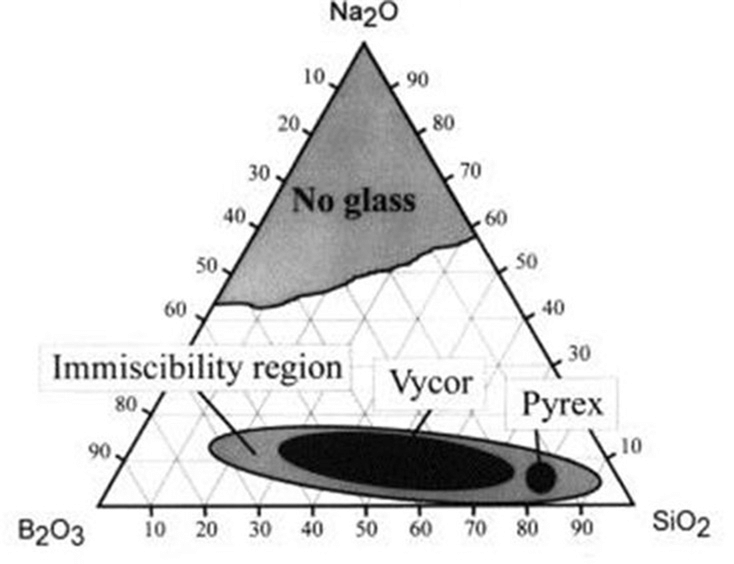
Simplified ternary phase diagram for the Na2O–B2O3–SiO2 system. The “Vycor” region corresponds to the phase separable mixtures that can be used to manufacture porous glass. (Bartl et al., 2001)
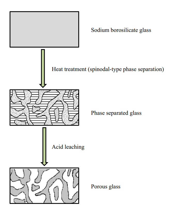
Schematic showing the formation of porous glass from a phase separated alkali (sodium) borosilicate mixture. (Hasanuzzaman et al 2016)

When the constituents of this mixture are tuned to specific concentrations and heated, the entire mixture undergoes an amorphous phase separation: the mixture transforms into two distinct phases.

One of these phases is an alkali-rich borate phase and the other a silica-rich glassy phase. Crucially, the borate phase is soluble in acid, while the silica phase is not. This means that, following heat treatment, the borate phase can be leached out with a hot acid solution. What remains is a highly pure and porous silica glass skeleton with large surface area: in other words, porous glass.

Controlling pore size

Acid-leaching of a phase-separated mixture generally results in a very narrow pore size distribution, earning the name “controlled-pore glass” and lending the resulting glasses to applications such as adsorptive chromatography of biomolecules.2

The average pore diameter is a function of heat treatment temperature and time, as well as glass composition. Thus, controlling the heat treatment temperature or time (or both) can easily produce porous glasses with a range of pore sizes to suit different applications. Glasses formed via these methods generally have pore diameters in the region of 1 to 1000 nm.3,4

Formation of porous glass using alkali borate systems can also be achieved without inducing a high-temperature phase separation: directly etching the surface of the glass can result in the formation of small pores (1-2 nm) restricted to the surface of the glass.

Other manufacturing routes

Porous glass can also be manufactured by glass sintering or via sol-gel routes. Glass sintering is widely used to produce glass foams with pore diameters in the region of 400 m to 1 mm. In sol-gel processes, a solution of organic monomers (sol) is turned into a glass by removal of the liquid phase. Sol-gel processes have been used successfully to create a range of pore sizes for different applications5,6 and they are becoming more common methods.

Applications of Porous Glasses

Porous glass provides an alternative to fused quartz which is comparatively difficult to produce and form into different geometries. However, many emerging applications make use of the functionality offered by the pores themselves. The high surface area and tailorable pore size distribution of these glasses make porous silica a highly effective filtering material, capable of separating not only the basis of molecular size but also of molecule type.7 This, along with a wide range of possible geometries, has made them useful in biosciences and chemistry.1

For example:

  • Enzyme immobilization and size exclusion chromatography techniques have been developed using porous glass; making use of its extreme chemical inertness, optical transparency, and small pore diameters.5,8,9
  • Surface-functionalization of controlled-pore glass using polyaniline has been used to develop optical chemosensors.10
  • Using additives to finely tune the size of pores can result in functional size-selective catalyst supports.11,12
  • The role of porous glass in targeted drug delivery has been studied, using porous-wall hollow glass microspheres. The spheres provide a porous, inert shell for the introduction and release of drugs inside the body.13
  • Porous glass is also being investigated as a bio-scaffold. These applications make use of the porosity, strength, corrosion-resistance, and biocompatibility of porous glass.14,15

All of these applications are made possible by the tunability of pore size, which enables specific physical properties to be imparted in the glass during the manufacturing process.

Mo-Sci produces high purity (> 98% SiO2 and < 2% B2O3porous glass frit and spheres suitable for applications in industry and research. Contact us to speak with one of our experts about your project requirements.

References and Further Reading

  1. Hasanuzzaman, M., Rafferty, A., Sajjia, M. & Olabi, A.-G. Production and Treatment of Porous Glass Materials for Advanced Usage. in Reference Module in Materials Science and Materials Engineering (Elsevier, 2016). doi:10.1016/b978-0-12-803581-8.03999-0
  2. Elmer, T. H. Porous and Reconstructed Glasses. in Engineered Materials Handbook (1992).
  3. Zhu, B. et al. Synthesis and Applications of Porous Glass. J. Shanghai Jiaotong Univ. 24, 681–698 (2019).
  4. Enke, D., Janowski, F. & Schwieger, W. Porous glasses in the 21st century-a short review. Microporous Mesoporous Mater. 60, 19–30 (2003).
  5. Lubda, D., Cabrera, K., Nakanishi, K. & Minakuchi, H. SOL-GEL PRODUCTS NEWS Monolithic HPLC Silica ColumnsJournal of Sol-Gel Science and Technology 23, (2002).
  6. Baino, F., Fiume, E., Miola, M. & Verné, E. Bioactive sol-gel glasses: Processing, properties, and applications. Int. J. Appl. Ceram. Technol. 15, 841–860 (2018).
  7. Hammel, J. J. & Allersma, T. United States Patent | Thermally stable and crush resistant microporous glass catalyst supports and methods of making. 923, 341 (1975).
  8. Du, W. F., Kuraoka, K., Akai, T. & Yazawa, T. Effect of additive ZrO2 on spinodal phase separation and pore distribution of borosilicate glasses. J. Phys. Chem. B 105, 11949–11954 (2001).
  9. Jungbauer, A. Chromatographic media for bioseparation. Journal of Chromatography A 1065, 3–12 (2005).
  10. Sotomayor, P. T. et al. Construction and evaluation of an optical pH sensor based on polyaniline-porous Vycor glass nanocomposite. in Sensors and Actuators, B: Chemical 74, 157–162 (2001).
  11. Takahashi, T., Yanagimoto, Y., Matsuoka, T. & Kai, T. Hydrogenation activity of benzenes on nickel catalysts supported on porous glass prepared from borosilicate glass with small amounts of metal oxides. Microporous Mater. 6, 189–194 (1996).
  12. Gronchi, P., Kaddouri, A., Centola, P. & Del Rosso, R. Synthesis of nickel supported catalysts for hydrogen production by sol-gel method. in Journal of Sol-Gel Science and Technology 26, 843–846 (Springer, 2003).
  13. Using Porous Glass Microspheres for Targeted Drug Delivery Mo-Sci Corporation. Available at: https://mo-sci.com/porous-glass-microsphers-targeted-drug-delivery/. (Accessed: 2nd September 2020)
  14. Rahaman, M. N. et al. Bioactive glass in tissue engineering. Acta Biomater. 7, 2355–2373 (2011).
  15. Fu, Q., Saiz, E. & Tomsia, A. P. Bioinspired strong and highly porous glass scaffolds. Adv. Funct. Mater. 21, 1058–1063 (2011).