Showing posts with label Breaks. Show all posts

Wednesday, 9 October 2024

Heat Up Soaks

Photo credit: Bullseye Glass Co.


It is often advocated that there should be a soak at the strain point to even out the temperature throughout the glass.

My question continues to be why? 

The glass has survived whatever rate has been used up to that point during its brittle phase.  So, it already has every chance of surviving a rapid rate during the plastic phase.

Instead of a soak at the strain point, Bob Leatherbarrow indicates a soak during the brittle phase will be more successful in avoiding heat up breaks.  He has observed that heat up breaks are most likely to happen around 260ºC/500ºF.  Therefore, a soak in that region is most likely to be of use in evenly distributing the heat effectively through the glass rather than at a higher temperature.  He recommends up to a half hour soak there before proceeding at the same rate to the strain point (about 540ºC/1004ºF).  The ramp rate to this heat up soak in the brittle phase should be related to the thickness of the glass and the intended profile.

The thickness to be fired for is determined by the profile.  Rates for full and contour fusing can be as for the thickness before firing.  Rounded tack fuse needs to be fired as though twice as thick, and sharp tack or laminated fuse need to be fired as though 2.5 times.  More information on initial ramp rates to the strain point can be found in Low Temperature Kilnforming available from Bullseye and from Etsy


Wednesday, 17 July 2024

Bowl Split Analysis


The visual evidence relating to this enquiry is a sharp-edged break through the middle of the slumped piece. The two parts have slumped separately, and seem attached at the rim, leaving the middle opened.  A moderate slumping temperature was used to fire the piece at the bottom of a stacked kiln load.

This is used as an example of the kind of thinking required when investigating breaks in slumping.

The split occurred before the slump was complete. We know this because the pieces no longer fit exactly together.  This means the crack opened as the slump continued.  There is other evidence.

The opening of the crack cannot have happened at or after the annealing. It would have already formed to the mould in a whole state. It would break completely across, because it would be in a brittle state.  And the pieces would fit exactly together.  But they do not.

This piece was at the bottom of a stack of shelves in a deep kiln.  At the bottom, there is no radiant heat, only side heat.  This could be a major cause the kind of break described.

It is possible that the split was not across the whole piece.  At the bottom of the kiln, the glass is not receiving any radiant heat from the top.  It is getting radiant heat only from the sides of the kiln.  That means the edges were considerably hotter than the centre.  The edge may be in a plastic state while the centre is still in the brittle state.  The contrasts in expansions are often great enough to break a piece.

From the evidence we have, it can only be said the ramp rate was too fast for the conditions. 

This little exercise shows that a lot of information about layup, schedule, place in the kiln, and any other relevant variation on the usual, must be detailed when asking why something has not turned out as expected. 


Wednesday, 5 June 2024

Diagnosing Slump fractures

Once you have an initial idea of the source of the problem, think about it.  Test it against the evidence.  Is there enough evidence to make a call?  Make sure you have considered alternative explanations.  It is just too easy to make a snap decision about causes in low temperature processes.  The source of breaks in slumping are most often complex and stem from interrelated factors.

I give you an example of the difficulties of diagnosing a slumping break.

On a Facebook group a person showed the break of a single layer on a cyclone mould.  Others commented the same had happened to them.


Picture credit: Esther Mulvihill Pickens

Possible causes suggested on Facebook included:

  • Thermal shock on the way up
  • Thermal shock on the way down
  • Too large on the mould and broke due to differential contraction
  • Too many holds on the way up
  • Too hot
  • Too thin
  • Follow the CPI programme
  • Glass extending over the sides

Some of these suggestions were of general applicability, some in relation to the state of the broken glass.

The suggestions did not include:

  • Cause of the rounded dots at the bottom of the mould.
  • A cause for the state of the flat piece off the mould (it appears sharp edged.  Does it show some forming already?).
  • The cause for the location of the fully formed remaining glass.
  • The effect of the location of the mould and glass in the kiln.
  • The consequences of a short soak at top temperature. 
  • Is the kiln running hotter than most (1290ºF/698ºC for 10 minutes at top temperature was used)?

Of course, it is difficult to diagnose a problem from just one picture. It is difficult even with many pictures. And so, without handling the object, only suggestions can be made.

But….

You must spend enough time examining the piece with whatever other information is available to make specific suggestions.  The first thought may not consider all the factors.  Consider what kinds of causes there are for breaks during or after slumping.

More close inspection reveals the rounded edges of the break.  That supports the idea that the temperature was too high. It also supports the diagnosis that the break occurred on the heat up.

The edges of the piece that has fallen off the mould, and now rests on the shelf, seem to be square or sharp. This shows the extent of the difference of temperature between shelf and top of the mould – less than 100mm/4 inches.  Also, how small the differences in temperature are between slump and tack.  The extent of difference in fusing does depend on how high in the kiln the mould is placed.  That is demonstrated here by the different elevation of the two pieces. 

The conformation of the glass to the mould is complete.  This supports the diagnosis of the break occurring early in the firing, and certainly before the slump was complete.  These pieces will not fit together.  So, even if the edges were sharp the fact they will not fit together shows they conformed independently to the mould surface.  Therefore, the break was before forming temperature was reached.

The glass hangs over the mould edges on only three sides and at an angle.  This indicates the cause of the overhang was the break.  Not the reverse. An overhang at the beginning of the slump is likely to be even.

The piece on the floor of the kiln combined with the movement of the glass toward the back gives an indication that the origin of the break is at the front.  This relates to uneven temperatures and to the placement of the mould.

No one mentioned the placement of the mould and glass at the back of the kiln.  This will have an effect on scheduling.  The mould and glass are very large in relation to the kiln.  There is little space between the glass on the mould and the walls of the kiln.  Also, the mould is placed asymmetrically in the kiln – very close on three sides.  This will cause uneven heating in any kiln.  To have a successful firing of glass on this mould in this kiln will require radically different schedules to that for a centrally placed mould that is moderate for the size of the kiln.

The large size (relative to the kiln) and the asymmetrical placing are the causes of the break, in my opinion.  I admit that it took me several looks to realise the placement was a key cause of the break.

So, the generalised comments about thermal shock are correct, but not as to the cause of that shock.  The kiln will be hotter in the central part and cooler at the corners.  This is true of all rectangular kilns.  The important thing is to learn how to cope with these temperature differences.

Slow firings to low temperatures with long soaks are the three important elements.  These make up the heat work of the kiln. Applying this to a schedule means:

  • slow ramp up rates – as little as one half the recommended rates for centrally placed moulds that are moderately sized in relation to the kiln.
  • Low temperatures present lesser risks to the control of the outcome of the firing.  Determining the lower temperature possible requires peeking into the kiln to monitor the progress of the firing.
  • Long soaks combined with low temperatures get the kilnforming done with minimal marking of the underside.  Low temperature soaks - in excess of 30 minutes - are required to minimise the marking.  Observation of the slump will be necessary to determine when it is complete.

My suggestions for the causes of other elements are:

·        Cause of the rounded dots at the bottom of the mould.

The temperature was too high. 698ºC/1290ºF is much hotter than needed for a slump. It was hot enough to round edges and small shards of glass.  Which shows excessive heat was received by the glass.

·        A cause for the state of the flat piece off the mould (it appears sharp edged. Does it show some forming already?)

The soak of 10 minutes was too short for the temperature in the kiln to equalise from top to bottom.  The glass on the shelf may not have reached 650ºC/1200ºF with such a short soak.

·        The cause for the location of the fully formed remaining glass.

The glass broke and was forced apart by the size of the expansion differences within the glass.  The movement of a piece at the front of the mould combined with the rearward and side movement of the glass indicate the origin of the break was at the front.  The distance apart shows the amount of force, and so the degree of reduction in the ramp rate required to fire this successfully.

·        The effect of the location of the mould and glass in the back of the kiln has already been discussed.

·         The consequences of a short soak at top temperature.

A high temperature is often considered necessary to pick up all the detail in moulds, whether slump or texture moulds.  The same effect can be achieved at lower temperatures with longer soaks.  The results of this strategy are fewer mould marks on the bottom of the work.

·        Is the kiln running hotter than most (Used 1290F/698C for 10 minutes at top temperature)?

This is one that cannot be answered other than by experiments carried out by the owner of the kiln.  Look at the Bullseye Tech Note #1 Knowing your Kiln for methods of testing temperatures. 

In short:

Diagnosis of slumping breaks is more complex than it appears at first.


More information is available in the eBook Low Temperature Kilnforming, an Evidence Based Approach to Scheduling.

This is available from Bullseye or Etsy


Wednesday, 6 March 2024

Slumping Strategy

A schedule was presented for a slumping problem of a 6mm/0.25” blank.  It consisted of three segments each of a rate of 277C/500F with short holds up to 399C/750F and then a rapid rise to 745C/1375F.  The cool was done with two long holds at 537C/1000F and 482C/900F followed by cooling rates for 12mm/0.5”


My response was that, yes it was fired too high.  Not only that, but the firing strategy, as shown by the schedule, is odd. 

Strategy

The general strategy for slumping follows these ideas.

·        Glass is slow to absorb heat, and in one sense, this schedule accepts that by having short soaks at intervals.  As glass is slow to absorb heat, it is necessary to use slow ramp rates and without pauses and changes in rates.  This should be applied all the way to the slumping temperature.

·        Holds of short durations are not effective at any stage in a slumping firing.  The objective is to allow the glass time to form to the mould with as little marking as possible.  This implies slow rates to low temperatures with significant holds at appropriate stages.  This about putting enough heat work into the glass that higher temperatures are not needed.

·        This kind of firing requires observation for new moulds and new arrangements of glass to ensure the slump is complete.  Once you know the mould requirements and are repeating the layup of the glass, the firing records will tell you what rates and times to use to get a complete slump with minimum marking.

·        The hold at annealing temperature is to equalise the temperature throughout the glass to produce a stress-free result.  Any soaks above are negated or repeated by the necessary soak at the annealing temperature.  The hold there must be long enough to complete the temperature equalisation that is the annealing.

·        My work has shown that annealing for one (3mm/0.125”) layer thicker produces a piece with less stress.  This indicates that a 6mm/0.25” piece should be annealed as for 9mm/0.35” to get the best result.

The summary of the firing strategy for slumping is:

  • ·        A single ramp of a slow rate to the slumping temperature.
  • ·        Observation of the progress of the slump to determine the lowest practical temperature and hold time.
  • ·        Annealing for one layer thicker that being slumped.
  • ·        Three stage cooling of the piece at rates related to the annealing hold.

Critique

This is a critique of the schedule. For comparison, my schedule for a full fused 6mm blank would be different.

  • ·        140ºC/250ºF to 677º/1250ºF for 30 to 45 minutes.
  • ·        9999 to 482ºC/900ºF for 1.5 hours
  • ·        69ºC/124ºF to 427ºC/800ºF, no hold
  • ·        125ºC/225ºF to 371ºC/700ºF, no hold
  • ·        330ºC/600ºF to room temperature, off.

The rate of the published schedule is fast for a full fused blank and extremely fast for a tack fused blank. This needs to be slowed.  The schedule provides a single (fast) rate of heating, but with unnecessary holds.  The holds are so short as to be ineffective, anyway. There is no need for the holds on the way up to the slumping temperature.  In general slumping schedules are of fewer segments.   This is because glass behaves well with steady slow inputs of heat.

Then strangely, the schedule increases the rate to top temperature.  It does so with a brief soak at 593ºC/1100ºF.  This fast rate of 333ºC/ 600ºF begins at 400ºC/750ºF.  This is still in the brittle phase of the glass and risks breaking the glass.  The brittle stage ends around 540ºC/ 1005ºF.

This rapid rate softens the surface and edges of the glass without allowing time for the underside to catch up.  This explains uneven edges.  It also risks breaking the glass from too great expansion of the top before the bottom.

Additionally, the schedule uses a temperature more than 55ºC/100ºF above what is a reasonable highest slumping temperature.  The top temperature of this schedule is in the tack fusing range.

There is no need for a hold 55ºC/100ºF above annealing soak. It is the annealing soak that equalises the temperature before the cool begins.  The higher temperature equalisation is negated by the cooler soak at annealing temperature. So, the hold at the higher temperature and slow cool to the annealing temperature only delays the firing by about two hours.  It does not have any effect on the final piece.

The schedule is cooling for a piece of 12mm/0.5”.  This is slower than necessary.  As noted above, cooling for one layer thicker than the piece is advisable to get the most stress free result.  The annealing soak could be 1.5 hours following this idea.  Cooling with a three stage schedule reduces the risk of inducing temporary stresses that might break the glass.  Although the initial cooling rate I recommend is very similar to this schedule, it safely reduces the total cooling time.

  • ·        69ºC/124ºF to 427ºC/800ºF, no hold
  • ·        125ºC/225ºF to 371ºC/700ºF, no hold
  • ·        330ºC/600ºF to room temperature, off.

Using my kind of schedule for the first time will require peeking once top temperature is reached to determine when the slump is complete. It may take as much as an hour. Be prepared to either extend the hold, or to skip to the next segment if complete earlier. The controller manual will explain how.

 More information is given in Low Temperature Kilnforming, An Evidence-based guide to scheduling.  Available from Etsy and Bullseye


Wednesday, 21 February 2024

Go-to Schedules

 It’s a schedule I always use.

This is a frequent statement in response to a firing that has gone wrong.

You don't always fuse the same thing, or the same design, or the same thickness, etc. So why always use the same schedule?

The schedule for the firing each piece needs to be assessed individually. It may be similar to previous firings. But it may have differences. Assess what those differences mean for the firing.  Some factors to consider.

Addition of another layer to a stack in tack fusing makes a difference to the firing requirements. Even if it is only on part of the piece. It needs to have a slower ramp rate and a longer anneal soak and slower cooling.

A different design will make a difference in firing requirements too. For example, if you are adding a design to the edges of the glass, you will need different bubble squeeze schedules than when you do not have a border. It will need to be slower and longer than usual.

The placement of the piece in the kiln may require a re-think of the schedule too. If the piece is near the edge of the kiln shelf, or in a cool part of the kiln while others are more central, the same schedule is unlikely to work. You need to slow the schedule to account for the different heat work each piece will receive during the firing.

If you have introduced a strong contrast of colour or mixed transparent and opalescent glass in a different way, you may need slower heat ups and longer cools.

These are some examples of why the same schedule does not work all the time. It works for pieces that are the same. But it does not work for pieces that are different. And we should not expect it to.

There are sources to help in developing appropriate schedules. Bob Leatherbarrow’s book FiringSchedules for Kilnformed Glass is an excellent one.

Another one is especially good for lower temperature work: Low Temperature Kilnforming, anEvidence-Based Approach to Scheduling. Be aware that I have a vested interest here – I wrote it.


Wednesday, 17 January 2024

Mending a crack

 I had a piece crack due to an annealing oops. I put powder on it and put it back in at a higher temp with a much longer anneal time. It looks great on the front, but I can still see where the crack was on the back. Is it supposed to be like that? I didn't think to put powder on that side.

If you think about why you get crisp lines at the bottom of a strip construction and a more fluid appearance on the top, you will be near the answer of why a repair looks ok on top but shows the crack on the bottom. The temperature on the bottom of the glass is less than on the top at the working temperature. And less again than the air temperature which we measure. This means that the bottom part of the glass has less chance to fully recombine. This, combined with the resistance to movement of the glass along the shelf, results in evidence of the crack being maintained.

Credit: Clearwater Glass Studio


There are some things that can be done to minimise the evidence of the crack. Make sure you know why your piece cracked before you try to mend it. An annealing crack will need different treatment than a thermal shock crack or a compatibility crack. Simply refiring the piece may only make the problem worse.

One approach is to place a sheet underneath. Make sure the broken glass is well cleaned and firmly pushed together. Dams may be useful to keep the glass compressed together. Glass expands both horizontally and vertically during the fusing process. Confining the glass will transfer most of the expansion in a vertical direction. This additional (small) vertical movement may help in forming the glass seamlessly. The broken glass now being supported by an unbroken sheet will enable the movement required to “heal” the crack.


If you do not want to change the surface, you can fire upside down. To do this you need to have a loose bed of powdered kiln wash, or whiting (a form of chalk) that is thick enough to press the textured side fully into the separator. Make sure the glass is pressed together without any separator getting into the crack. One way to ensure the crack does not open is to use a small amount of cyanoacrylate (super) glue which will burn away during the firing.  Put a sheet of clear glass over and fire. Thoroughly clean the face after this repair firing. The ultimate top needs to be fire polished to remove the evidence of the crack, and if it has picked up any marks from the powder.

You could, of course, fire upside down in this way but without the additional sheet, to avoid making the piece any thicker. This may or may not work well. If the base layer is one layer thick, it may pull in at the sides and pull apart at the crack where it is one layer thick.  It is also possible that bubbles will develop in the thin parts of tack glass because of the uneven thicknesses.

A final note. Placing powder on the back will not improve things. The powder will not fully incorporate with the glass and so leave a rough surface without concealing the crack.

Avoiding breaks

To repair or not

The process of repairing

Wednesday, 10 January 2024

Identification of Mechanical and Thermal Stress

The Identification of stress is important in investigating the causes of stress. We have well established clues to help us with our glass selection and alteration of our firing schedules. We can get more information about why the cold glass has broken from the scientific literature. The manufacturers of float glass and the installers of large panes investigate thoroughly the causes of breaks in glass that has been installed. 

One article - Breaking It Down, Why Did the Glass Break? by Timothy Bellovary from Vitro Architectural Glass - looks at mechanical and thermal stress and distinguishing between the two.  This post is quoted extracts from that article. [Text in square brackets are interpolations of mine].   Note that all the illustrations are from the article and are copyrighted.

Source: https://vcn.vitroglazings.com/technical-forumdiagnosing-glass-breakage

Identifying the break origin can provide hints about the following:

·         Mode of glass failure—Was it mechanical or thermally induced stress?

·         The stress or tension level at which the breakage occurred.

·         Other contributing factors—were there digs (deep, short scratches) resulting from glass-to-glass or glass-to-metal contact? Did a projectile hit the glass? Is there edge or surface damage?


To find the origin of a break, the first step is to assess its direction by inspecting the fracture lines… in the glass. These rib-shaped marks, distinguished by a wave-like pattern, begin at the break origin and radiate along break branches, and almost always project into the concave face of these lines.


Figure 1
Diagram of Fracture Line Direction


It’s often helpful to make a basic diagram (see Figure 1) of the fracture lines. … The origin of the break can be determined by:

·         Drawing arrows (indicating fracture line direction) pointing into the concave face of break wave markings in the glass edge.

·         Tracing point-to-tail of arrows back to the break origin.


Mechanical Stress

Low-stress tension breaks are experienced most frequently by residential window and IGU manufacturers. The origin of the break is typically at damaged areas of the edge or surfaces near the edge, such as digs, scratches or chips. In many cases, breakage from damaged glass occurs after the initial edge damage is incurred, such as during IGU fabrication, sashing operations, transportation, job-site handling or storage, or the installation process.

In Figure 2, the break origin is not 90 degrees to the edge of the glass, indicating a tension break caused by bending. Low-stress, mechanical tension breaks often occur from bending at less than 1,500 psi.

Figure 2

Low-Stress Mechanical Tension Break


High-stress tension breaks share one characteristic with low-stress tension breaks: The break origin is not 90 degrees to the edge of the glass, suggesting a tension break caused by bending. However, additional branching of the crack within two inches of the break origin (see Figure 3) indicates that the stress at breakage was likely higher than 1,500 psi.


Figure 3

High-Stress Mechanical Tension Break


Thermal Stress

Thermal stress breaks often originate at the edge of the glass and form virtually 90-degree angles to the edge and surface of the glass.

As with mechanical stress, there are two types of thermal stress breaks: low stress and high stress.


Figure 4

Low-Stress Thermal Break

Low-stress thermal breaks are often indicated by a single break line starting at the break origin point at or near the glass edge and propagating two inches or more before branching into more break lines (see Figure 4). Damaged glass edges are the most frequent cause of low-stress thermal breakage.


High-stress thermal breaks appear as a single break line starting at the break origin point at or near the glass edge and generally branching into additional breaks within two inches [50mm] of the origin. This indicates a breakage brought on by conditions that cause high thermal stress, such as severe outdoor shading on parts of the glazing; heating registers located between the glass and indoor shading devices; closed, light-colored drapes located close to the glass; or glazing in massive concrete, stone or similar framing.


Figure 5

High-Stress Thermal Break

Analysing the Break Origin

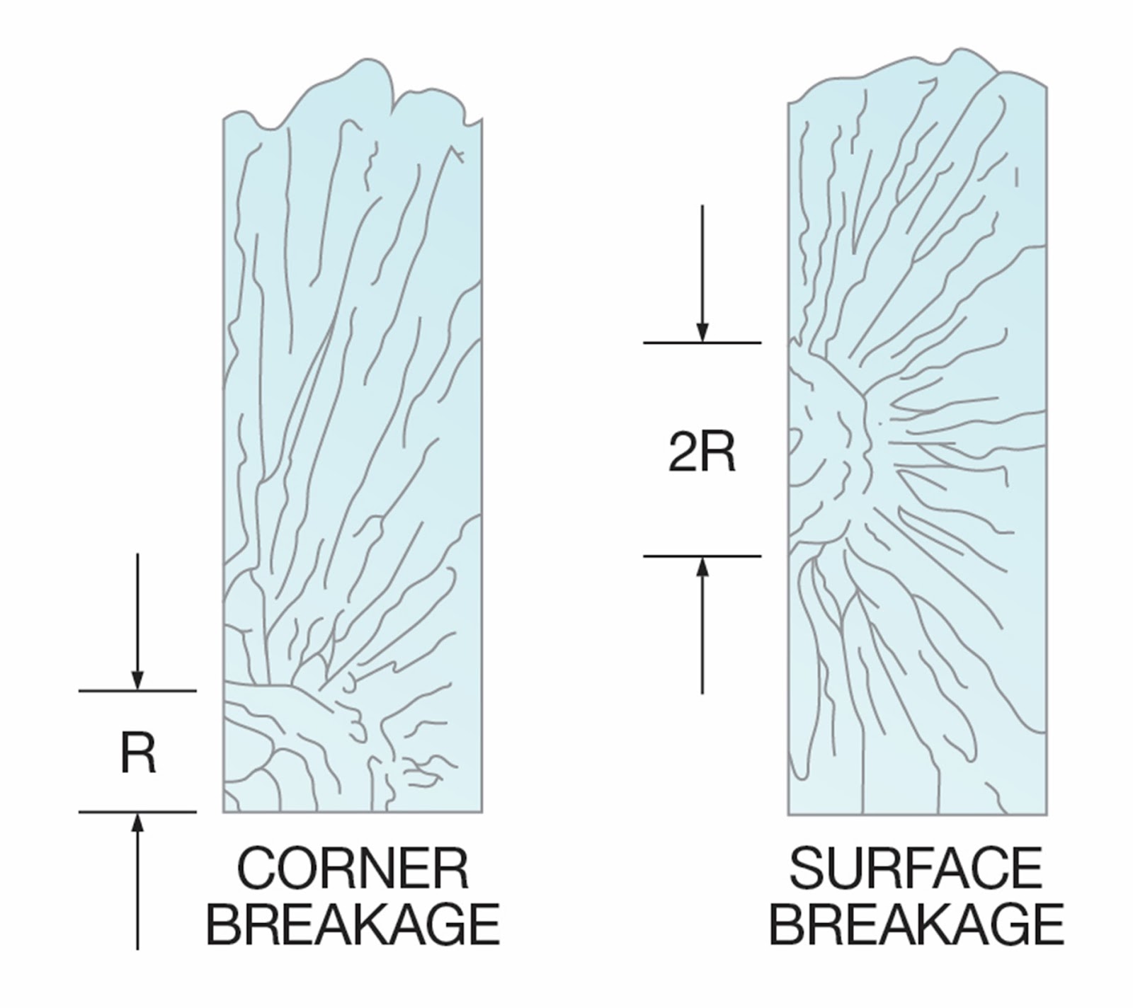
A reliable method for estimating the stress level of a break at failure is a mirror radius measurement. Radius dimensions are determined by crack propagation velocity characteristics.

A crack propagates itself through glass with increasing velocity as it moves further from the point of origin. If an object has sufficient energy to propagate a crack through the thickness of the glass, then a “spider web” pattern will form. ….

Near the point of origin, a smooth, mirror-like appearance on the fracture face indicates a low crack velocity. However, as velocity increases (due to higher tension stress), the fracture face takes on a frosted look; then, at the highest velocity, it assumes a ragged or hackled appearance. Mirror radii appear in various forms, depending on the stress level of the fracture.

Figure 6 shows break origins resulting from high tensile stresses, such as bending or thermal stress breaks.

Figure 6

High-Stress Mirror Radii
(R = Mirror radii)


Figure 7 represents the break origins of glass fracturing at low bending stresses. In this example, a smooth fracture face forms across the thickness of the substrate. When the breaking stress is low, the mirror radius is often radial and may extend deeply into the substrate.

Figure 7

Low-Stress Mirror Radii
(R = Mirror radii)


To identify what damaged the glass in the first place, four factors are examined during this analysis:

·         Impact

·         Inclusions

·         Thermal variance

·         Pressure differentials

Impact

Identifying the nature of the breakage pattern can determine whether a foreign object hit the glass and whether the impact was perpendicular or parallel.

Depending on the severity of the impact, the immediate area surrounding the break origin might be cracked, crushed or missing.

                 
Figure 9

High-Stress Mechanical Breakage

[This pattern of break is often exhibited when the separator fails or is insufficient to keep the glass from sticking to the ceramic support shelf.] …

Inclusions

Any undesirable material embedded in glass is considered an inclusion. ... [In general, kilnformers place inclusions within the glass and know the risks of breaks].

Thermal Variance

[This article relates to float glass installations, but the principle remains.] If the temperature difference across a [piece] of glass is great enough, the accompanying stresses can reach levels that cause breakage. … The combination of contact, surface damage and localized temperature gradients can greatly increase the likelihood of breakage.

Pressure Differentials

[This section applies mainly to Insulated Glazing Units. It points out that differences in altitude between the manufacturing and installation sites – in combination with temperature – can cause breaks. It is not of primary importance to most kilnforming, but something which should be considered when installing kilnformed glass in an IGU]

Conclusion

[Occasionally] glass breaks for no obvious reason. Whether it’s a one-off or part of a continuing pattern of incidents, glass breakage is inconvenient, potentially dangerous and costly. … Conducting “post-mortems” on glass breaks helps investigators identify the general reasons for each incident, including the type of failure that caused the break, and the potential original source of the damage. By using the techniques outlined in this article, [kilnformers] may be able to accurately identify the likely origin of such failures and … use that information to prevent future occurrences.

https://vcn.vitroglazings.com/technical-forumdiagnosing-glass-breakage

[An important element in identifying breaks in kilnforming that this article demonstrates is the difference in the angle of the break. A 90 degree angle to the surface indicates a thermal cause to the break. The more branching of the lines of breakage, the greater the stress. The branching breaks indicate there was significant temperature difference.

The breaks which are less than a right angle to the surface indicate a mechanical origin of the stress. This is usually the glass breaking at a weak point when subject to a bending stress.

If the point of origin of the stress can be identified as demonstrated in the article, it may help in determining causes. One of these causes might be hot or cold spots in the kiln.]


Wednesday, 15 November 2023

Inadequate Annealing - Effects on Next Firing

Credit:

https://immermanglass.com/about-kilnforming/cracks/


The speculation about breaks caused by inadequate annealing of the piece on the previous firing is common.  I do not know if this can be proved to be inaccurate, but we should think about it.

A parallel condition to this poor annealing is toughened/tempered glass which is under a lot of stress between the inside and outside surface of the glass. As Bob Leatherbarrow mentioned to me, we can heat up the highly stressed toughened glass without breaking it by using moderate ramp rates. During this heat up in the brittle phase, the stress is gradually relieved. It does require the moderate ramp rates, of course. 

This parallel circumstance of heating toughened/tempered glass which is highly stressed raises the question: Why should mildly stressed kilnformed glass suffer breakage, if fired at a reasonable rate? Highly stressed toughened/tempered glass does not.

If we apply the experience of relieving the stress in toughened/tempered glass, you can see how inadequately annealed glass behaves. The under-annealed glass has stress distributed (possibly unevenly) across its substance. As the glass temperature moves toward the strain point it becomes less brittle and the stresses are reduced. By the time the glass reaches the strain point, the stresses from poor annealing are relieved.

Any glass not fired slowly enough for its thickness or layup toward 300˚C/573˚F will break. This has been observed to occur around 260˚C/500˚F.  This most commonly occurs in pieces that are laid up with different thicknesses  across the surface. The heat cannot reach the bottom layers as quickly as the overlying ones. The expansion of covered and uncovered glass - due to the heat exposure - is to different.

Thinking about the behaviour of glass in this way indicates that breaks early in the firing relate to a too rapid ramp rate, not necessarily a previous annealing problem. We should, of course, be checking on the stress in our pieces after each firing. This will alert us to the amount of stress in the piece and so to be more cautious in the ramp rate and in the annealing during the current firing. 

Speculation about inadequate annealing in a previous firing as a cause of breaks is misplaced. The thinking that stress will carry through the heat-up and cause breakage is misdirected. 

More information on this is available in the eBook LowTemperature Kilnforming, an Evidence-Based Approach to Scheduling at Etsy VerrierStudio shop and from Bullseye Ebooks.


Wednesday, 9 August 2023

Fixing a Broken Piece


This conversation is reproduced by permission (with some editing out of extraneous information). It is presented as an example of how conducting a critique of your schedule can have dramatic effects on the results of your firing. 


This is the piece as it came out of the kiln.

Picture credit: Ike Garson

You may have seen the photo I posted of a large copper blue streaky piece that has cracked right across. …  I’m wondering if it would be better trying to bring the 2 pieces together instead of opening up the 2 pieces and inserting frit. I was thinking of firing it with a tack or contour schedule.

This is the crack that developed later through the frit and single layer centre.

Picture credit: Ike Garson


I have 4 questions:

A.   Even if I manage to fix it, do you think that fissure line will always be too weak and liable to break off at any point?

The strength of the joint will be dependent on the firing conditions.  To make it strong, the temperature should go to full fuse.  Tack fusing will leave the joint more visible and weaker.  To stop the joint rounding during heat up, you will need to dam the piece tightly to stop the normal expansion of the glass and ensure the glass is forced together during the higher temperatures.

B.     I have some large pieces of clear confetti. Would it benefit using them to bridge the 2 sections from below?

Anything you put on the bottom will have distinct outlines and visibility.  The temperature on the bottom can be 10C or more different from the top surface, which is why you can get crisp lines with the flip and fire technique.

C.    Would clear powder hide the crack or would it always be visible after firing?

Any additions to the top may be less visible, but adding clear powder makes the join more obvious.  You need to use powder of the same colour as the sheet glass.  Since you are using a streaky glass, you can’t use coloured power either as it is very difficult to imitate the steaks even with powders of the same colours. 

More information was given indicating the first contour fuse schedule in Celsius:

  1. 260 730 00.20
  2. FULL 515 00.60
  3. 260 150 End

This is the contour schedule I have used many times successfully but never for a piece during this week.

My critique of the schedule. 

Segment 1.

  • ·    It is too fast for the small distance to the side of the kiln. 
  • ·    It is too fast for a piece of varying thicknesses. Most expansion breaks occur above 300˚C, so a soak at ca.260˚C will help ensure the glass maintains an even temperature, especially with large differences in thickness. Then you can advance more quickly. 
  • ·   There is no bubble squeeze.
  • ·   The top temperature seems low for a good tack, or the soak is a bit short.  Long soaks allow the glass molecules to bind at the atomic level firmly. This is the principle used in pate de verre.
  • ·   It definitely needs to be on fibre paper covered with thinfire to allow air out.

Segment 2.

  • ·   The soak at 515˚C is better done at 482˚C for Bullseye.
  • ·   My tests have shown that contour firing a piece like this at rates and holds for 1.5 times the height of the piece is necessary for good results.

Segment 3.

  • ·   Also, my tests have shown that a three-stage cooling provides the best result.  Slow cooling keeps the glass within the 5°C difference required for avoiding stress.
  • ·   Annealing at the bottom end of the range combined with an appropriate length of soak and slow cooling gives a denser glass than soaking at the middle of the annealing range. 
  • ·   The best cooling comes from a three-stage cooling process.  This involves a slow rate for the first 55C, a rate of 1.8 times this for the second 55C, and a rate of 3 times this for the final cool to room temperature.

These points mean that I would recommend you fire for at least 10mm thick.  This recommendation is for a new piece, not a repair. In this repair case and for the conditions, I would choose 12mm as being more cautious. My schedule would look something like:

  1. 120˚C to 260˚C, 20’
  2. 300˚C to top temperature, 10’
  3. Full to 482˚C, 120’
  4. 20˚C to 427˚C,0’
  5. 36˚C to 370˚C, 0’
  6. 120˚C to room temperature, off

The anneal soak is for a piece 12mm thick.  The cool rates are for 21mm thick.  This is to compensate for the nearness of the glass to the edge of the kiln.  It will help to ensure the glass does not have excess stress locked into the piece during the cooling.

D. Do you think this schedule would work [for a repair]? It's adapted from a standard tack schedule.

  1. 222 677 00.30
  2. 222 515 00.40
  3. FULL 482 01.30
  4. 63 371 ENDS

Critique of the schedule.

Segment 1. 

  • ·   Too fast given earlier difficulties. 
  • ·   Too low for good adhesion unless you use about 10 hours soak. 
  • ·   Even at sintering temperature (690°C) you would need 2 hours.  But at sintering temperature you do not alter the surface 

Segment 2. 

  • ·   Too slow a cool from top temperature and risks devitrification. Should be FULL.
  • ·   You do not need the soak at 515˚C.  It only delays the annealing process.  It seems this idea of soaking at the upper portion of the annealing range was introduced by Spectrum over 2 decades ago. 
  • ·   Any advantage that might be achieved by the higher soak is cancelled by the FULL rate to the annealing soak. 
  • ·   Go straight to the anneal soak. 

Segment 3. 

  • ·   You need a more controlled 3 stage cooling to get the best result.

My schedule for repair would look something like this:

  1. 120˚C to 540˚C, 10’
  2. 300˚C to 780˚C, 10’
  3. Full to 482˚C, 210’
  4. 20˚C to 427˚C,0’
  5. 36˚C to 370˚C, 0’
  6. 120˚C to room temperature, off

I am making the assumption that 780˚C is full fuse in your kiln.  Anything less than full fuse will certainly show the crack.


A Look at Causes.

  • ·  The piece is far enough away from the elements.  It is not on the floor. These are not the causes.
  • ·  It is very near the sides of the kiln.  These are always cooler than the centre. There is always a risk of breaking in this case.  Very slow rates are needed. 
  • ·  There is a 3.5 times difference in thickness within the piece. This also requires slow rates.
  • ·  If the break were to have been on the heat up these elements of uneven heating, and rapid rates are a problem.  But the break occurred after the cool down. So, the annealing soak and cool is a problem. 
  • ·  I have suggested some alterations to the schedules to address these things.


Fixing for Yourself

  • ·   Dam it tightly to avoid expansion within the glass as it heats.  This holds the join together and causes the glass to gain a little height. 
  • ·   Place the piece on 1mm or thicker fibre paper topped with thinfire.  This will help avoid a bubble forming in the clear.
  • ·   I have suggested a schedule which is slower to ensure no further breaks.  It is slow to the strain point and fast after that. 
  • ·   It needs to be a full fuse to fully join the two pieces and ensure it is sound.
  • ·   The cool to annealing should be FULL.  Eliminate the soak in the upper annealing range. The effects of the time spent there is nullified by the rapid rate to the main annealing soak. 
  • ·   Anneal as for 12mm, but with slower cool rates (for 21mm) to ensure there are no stresses built into the piece by the nearness of the glass to the edge of the kiln.
  • ·   These methods and schedules will make it a strong whole.  But the join will still show on the bottom. 
  • ·   After fixing, if you are still not satisfied, break it up for incorporation in other projects.

Finally, and unfortunately, I do not think it can be satisfactorily repaired for a client.  The crack will show on the back. You will know it is a repair, rather than a whole. And that will reflect on your feeling about the piece, and possibly your reputation.


Conclusion

The commission was successfully re-made from scratch by the artist using some of my suggestions on scheduling. This is the resulting piece.


Picture credit: Ike Garson


Careful analysis of the conditions around a break are important to making a successful piece in the future. Many factors were considered, but the focus became the schedule. Analysis of each step of the schedule led to changes that resulted in a successful piece with the original vision and new materials.