Showing posts with label Reinforcement. Show all posts

Friday, 27 March 2020

Reinforcement

Reinforcement is probably the most important design element in stained glass. Without adequate reinforcement, all other effort and results are secondary, because an inadequately reinforced work will not survive, and that is sad.

GuidelinesThere are no all-encompassing reinforcement rules. There are however some basic guidelines:
  • Restrict non-reinforced panels to between 2 and 4 perimeter metres (a rectangle of 1 by .5 meters up to a square of 1 meter).
  • An abundance of horizontal or vertical lead lines within the leading concept are most likely best served by a vertical reinforcement system.
  • A diagonal or bent reinforcement bar dilutes its reinforcement capacity in proportion as it deviates from the straight. Such supports serve to merely stiffen the section.
  • Know that most reinforcement systems provide only lateral reinforcement.
  • In most architectural situations which adhere to sections of 4 perimeter metres, reinforcement will usually be 12” to 18" apart in vertical accommodations, with an average around 15".
  • Placement of reinforcement should be established on the initial scale layout in which the design is to be done. It should not be an addition after the whole is designed. That increases the likelihood that the reinforcement will be an intrusion upon the design.
  • Very tall or wide windows should have an armature of some sort. This is commonly "T" bars for the panels to rest upon without transferring their weight to the panel below. Other more complicated armatures can be seen in large windows, such as at Canterbury Cathedral.

With diamond and other quarry lights, reinforcement placement cannot always be equally spaced. In such instances, it is probably best to have the shortest distances between the reinforcement at the base of the section where the weight creates the greatest likelihood of buckling.

Structural Reinforcement


Leaded light panels often require additional support against wind pressure or vibration. Whether this is needed depends on the size and location, e.g. if in a door or a ventilating window that is constantly being opened and shut.  Large leaded glass windows need some bracing against the force of wind and rain. This can be achieved by using one of the following supports:
  • Saddle Bar
  • Reinforcing Bar (Rebar)
  • Steel Core or Steels
  • Zinc Section

Saddle Bars are the strongest method of support and are used in large external windows for preventing panels from bowing inwards. They resist wind pressure in exposed situations. Saddle bars form part of the latteral support structure of the window. These bars are attached to the panel with copper or lead ties.  These ties are soldered to solder joints across the narrow width of the panels.  The bars are fixed to the perimeter of the opening either by the mouldings or by being inserted into holes in the frame. The sides of the opening provide the ancor points for the bar.  The panel is fixed to the bar by twisting the ties around it.


A saddle bar fixed in position at the side and the ties being twisted around the bar.


Sometimes the opening is divided by sideways "T" bars.  Generally the leg of the "T" faces outwards and the panel is set onto the ledge formed by the leg of the "T".  This leg often has a series of holes drilled in the leg, for pins to be inserted to hold the panel in place until the sealant has cured.


An example of "T" bars being used on a small side opening window


Rebar is another external support.  It generally is a zinc coated steel strap about 2mm by 10mm and asl long as needed to cross the panel.  This tends to be soldered directly to the panel at the solder joints either on the inside or outside. One advantage of this material is that it can be bent to conform to the lead lines of the panel.  In consequence it is not as stiff as saddle bars are.


Steel core
Steel cores take two forms - either steel-cored lead or steel strips fitted into the lead cames when leading.  The steel cored lead came is less available nowadays.  They are mainly used in domestic glazing where support is required particularly in leaded lights with diamond panes when they are inserted in continuous diagonal leads. The steel cores are not adaptable to significant curves.


Steel cored lead came cut away to show the steel core


Zinc

Zinc section came is often used to frame a panel that is not glazed into a window or frame. It has been used in the past for both straight and curved lines.  Using it for curves requires a came bending machine to give good, regular curves.  It gives a panel strength for ease of handling, but does not resist sagging or bowing at the centre.  The other disadvantage of zinc is that it corrodes much faster than lead.


Image showing a variety of zinc came

Wednesday, 27 January 2016

Does Wider Foil Give Greater Strength


The strongest part of a stained glass panel, whether leaded or copper foiled, is the glass.  The weaker points are the matrix that holds the panel together.

Of the matrix, the solder is the strong part.  The copper foil is weaker (and much thinner) and the adhesive is the weakest part of all.

A wider bead gives more apparent strength, but on the surface. It provides a broad line to grasp the glass.  But wide beads are often not what is visually desirable, nor practical.  And the wider the bead, the more solder will be used.

The most important part of a panel is the thin fin of solder between the top and bottom of the solder beads.  This is the connector between front and back. The strength of the whole panel depends on that fin.  So, it could be argued that very closely fitting foiled pieces lead to a weaker panel than loosely fitting ones.  I would not argue that, but it is important to have that connector of solder between the surface beads for a panel to be strong.


The solder connects the two solder beads together and forms the matrix which holds the panel together.

Here the fin of solder is a little thinner, so the matrix is marginally weaker


For larger panels, reinforcement will be required, either between the glass pieces, or on the surface.  The fact that reinforcement is so often used in the gap between the pieces, is confirmation that the fin of solder between the front and back is very important.

Monday, 25 February 2013

Hanging Sun Catchers


Unless you are using some manufactured system or a frame, the most frequent way to provide hanging points is to create a loop from copper wire.


Hangers should originate in a solder bead that goes some way into the piece. The loop's tail should lie a significant distance into the solder line to ensure it does not pull the piece apart. If this is to remain invisible, some planning will be required to allow the small extra space between the foiled glass.


The loops for hanging a piece of any size should not be soldered to the perimeter foil without reference to the solder bead lines, as the adhesive and foil are insufficient to hold the weight of the piece without tearing.

Here the hanging loops could have been moved just a little to engage with the solder joints at the left ear and at the tail to make stronger hanging points

Here the hanging points are at the solder joints giving strong hanging points

Reinforcement of free hanging or projecting elements can be done by placing wire around the piece with a significant excess going along the perimeter in both directions. The supporting wire can go into the solder line, if it is a continuation of an edge of the free hanging piece.

In this case a twisted copper wire around the perimeter gives strong hanging points

The strongest method is to wrap the wire around the whole perimeter of the piece. Choose easily bent copper wire. This will be pretty fine, but when soldered, will be strong enough support the whole piece.

The hanger can be made by leaving a loop of wire free. This way you can hang from any convenient place on the perimeter. This loop can be made by a single 180 degree twist in the wire, or by bending a loop into the perimeter wire. In all cases you will need to tin the wire to blend it with the rest of the piece.

This perimeter wire can be simply butted at the start/finish of the wire. It could be overlapped, but this is unnecessary on any piece where this method is adequate for support. The start can be at the top or bottom, although I prefer the top, so the wire is continuous from loop to loop. The reason for continuing beyond the loops is to provide support to all the edges of the sun catcher.

This single point hanger is at the strong point of the piece

The left hanger is strong, but the right is weaker than if it had been attached to the right of the body

This piece needs wire around the piece, especially to stabilise the tail and ears

Monday, 10 September 2012

Overlapping Joints

Overlapping Joints in paneled windows

In many installations of tall windows, such as churches or tall sidelights, there is a requirement for handling and transport that the window be built in panels, each of which sit on top of the other. There are some considerations about the design and installation of such windows.

The design has to allow for the additional thickness of at least two hearts at the joins of the panels.

The leaves of the upper leads should always overlap the lower leads to be able to shed water from the rain so it does not migrate inside.

There should be wide heart “H” leads on the bottom of each panel. These should be 12mm or 16mm wide heart flat leads on all except the bottom panel where the normal 5mm heart can be used.  The wide heart lead allows easy placing of the upper panel onto the lower one.  It is possible to open the leads of a standard heart lead, but it is much easier to use a wide heart lead.

The top leads on each panel should be flat leads of 10mm or “U” lead. This is largely preference. If you use “H” leads at the top, you should fold the leaves over, or cut them off, depending on the allowance in the design.

The openings should have glazing or saddle bars placed at the levels where the panels join. These need to be tied to the panels with tie wires soldered onto the panels. The ties on the panels should be soldered so that the ties on the bottom of the top panel point downwards, and the ties on the top of the bottom panels point upwards.  It is important that the soldering of the tie wire on the bottom panel is very flat and low enough to avoid interfering with the flange of the upper panel and to allow the easy setting of the top panel over the joint. It is also worthwhile to put a loop in the soldered end of the tie wires so they do not pull out of the solder joint.

Once you are certain of a good fit, set the upper panel down onto the lower one.  Dress down the opened flanges of the upper panel over the lower one.  Then draw the wires from the upper panel down behind the saddle bar, the lower wires up behind the saddle bar, fold over them over the saddle bar, twist firmly.  Cut the ends to uniform lengths and fold back the twist up and over the bar.  This secures the panels, draws the two panels together and provides lateral support to the window.

It is not necessary to putty the joint of the panels, as the flange of the upper lead is sufficient with a little dressing of the flanges flat to the lower panel to avoid any ingress of water.

Friday, 31 July 2009

Weaving in Leaded Glass

"Weaving" is only easily and fully done where there is a grid. The example below shows a restoration project where the main part of the panel is a grid.

This image shows the starting of the weaving. A short lead covering only one quarry has been placed horizontally - although you can start with a short vertical, both are fine. The next lead is vertical and covers two of the quarries. As you can see here the two quarries at the right are ready for the longer horizontal to be placed.


You proceed in this fashion - alternating long and short leads throughout the grid area.


As you can see this builds up in a diagonal fashion with each vertical and horizontal line being interrupted after every second piece of glass.


If you look closely you can also see that these leads are being tucked. This is easier with leads of 7mm and greater than of 6mm and less.
This method of leading gets its name from the similarity to representations of weaving in illustrations where a broken line represents the thread or reed going under another. Its purpose is to avoid hinges and so strengthen the whole panel. This avoidance of hinges makes the turning of the panel during soldering and cementing much easier.

Of course, you must remember that the glass is the strongest part of the panel.

Wednesday, 22 July 2009

Leaded Glass Reinforcements

I received a query recently about this subject. As the correspondence may be useful to a more general audience, I present an edited version here. (all the personal chat has been taken out!)

“I was wondering if I would be able to ask you a question regarding re-enforcements. In regards to the hollow lead with the bar running through or using Reforce with the brass molded through it. Which is better?”

The lead covered steel is stronger. It has the disadvantage that if it gets moisture into it, it will corrode. Steel expands when it corrodes. This leads to progressive destruction of the surrounding glass.

Brass is weaker, but does not have the same degree of expansion when corroding.

Steel is cheaper than brass.

These factors have to be taken into account when deciding on which to use. So I don’t have a definitive response for your situation.

Really any time you need to reinforce a panel, it is because it is too large to reliably support itself. Often this is because it is too tall or too wide. Big windows have always been built in sections, with each stacked upon top of the lower ones. There are saddle bars or ferramenta added to the window opening to strengthen the window.

It is important to note that in compression glass is much stronger than steel. It is when the glass is in tension that it is weaker. So what the reinforcement is doing is resisting any lateral movement. It is not holding the glass up. The glass can do that very well on its own. The glass is subject to lateral movement from wind pressures mostly. But in some situations as in doors, it is subject to inertial movements - the door closes and sometimes slams. In other installations there is vibration – such as sidelights. The re-enforcement is to counteract or reduce this movement.

In general, if the panel needs reinforcement, it is too large as a single panel, and needs to be built in several panels. Some people hate to have the line of the panel joints, but the eye generally ignores those straight lines (unless they are out of true horizontal or vertical).

Some questions you need to ask yourself about reinforcement are:
Do you really need to reinforce?
Must it be within the panel?
Can you use external support?
Why would two hinges be better than one?

Remember the reason for not having a hinge is because the glass is the strongest element in a leaded or copper foiled window. Therefore a window with complicated lines will be a stronger window as the glass interlocks. If you look at many older windows you will see a number of hinges, and the windows are still there. I attach an image of a stair window that has been in place for just under 100 years. It has a multiplicity of hinges. I am not saying don't concern yourself about hinges, but keep a sense of proportion.


Nowadays, I keep all my reinforcements to the surface of the panels, not inside. Also if you want to join panels in a large window, it is not essential that the join be horizontal or vertical. It could be in a wave, sinuous curve or in a stepped fashion. Your imagination is probably the limit here, not the material.


The enquirer then sent pictures with further information.

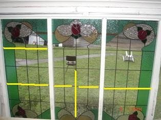
“These are the latest 3 panels I’ve made for my bungalow out the back. They measure 1100mm high by 500 wide approx. I’ve made them all with different reinforcement applications. I was told they would not need any but still wanted to strength them up.

“The middle you can see I broke the hinge line with two pieces of re-force and on the other two I’ve gone all the way through to the outer border. All other lead lines do not go more than 2 pieces of glass before they are crossed by another piece of lead to break up that hinge thing.

“Due to the size/design I’d appreciate your thoughts on what I’ve done being correct/overkill?”


The two outer panels are supported appropriately. I believe the right one is adequately reinforced, and the left is over reinforced, but there will be no harm. The middle one is not adequately reinforced. The broken horizontal reinforcement transfers the stresses to the middle. The vertical one also transfers the stresses to the middle, only a little higher.

For reinforcement to work, it needs to transfer the stresses to the sides/tops of the panel where they will be captured by the framing. Thus the reinforcement needs to be a continuous line. The strongest reinforcement will be across the shortest dimension of the opening.

The weaving of the lead lines described by you as “lead lines do not go more than 2 pieces of glass before they are crossed by another piece of lead to break up that hinge thing” is exactly the right thing to do in these panels.

In the case you are illustrating, there should be no problems for several generations at minimum and possibly for a century.


"I’ve also included one other piece I’ve designed and cut which is going to be installed in an internal wall inside a home. Its 800/800mm approx and due to it being kept out of the weather was wondering about what type of re-enforcement structure would suit?"


As this will be an internal panel, I suggest that the best reinforcement would be a toughened/tempered sheet of 4mm float glass installed behind the panel. This will provide support in case someone leans against it. Yes, there is a diagonal hinge at the trunk, but the strongest reinforcing for this would simply be a horizontal bar behind the panel, which would look ugly and I don't think you want anyway.


Wednesday, 14 January 2009

Reinforcement Materials and Methods

Variations in Reinforcement Materials and Methods

Be aware that every reinforcement situation is likely to vary. This is even more prevalent today with stained glass being more utilised in conditions which present varied structural situations.

External steel bars
There are many methods employed to provide reinforcement and a variety of mounting procedures. Surface reinforcement is probably best accomplished with flat cold-rolled galvanized steel bars either 3/8" or 1/2" in width by 1/8" thick. Since they are directly affixed to the solder joints of the section they disperse greater reinforcement than with 14 gauge copper tie wires attached to round or square bars which tend to stretch and consequently result in buckling from the sagging of the section.

Steels
Internal flat steel bars incorporated within the heart of the came are also of excellent service, especially in vertical instances. Horizontally they provide lateral reinforcement but likely no vertical resistance to sag.

Saddle bars
These are normally round or square steel bars that span the opening. The panel is inserted into the opening and blocked into place. The saddle bars are placed in the slots prepared in the sides or top and bottom of the opening, and the copper ties already soldered to the panel’s joints are twisted round the bar.

T bars
These are “T” shaped bars attached to the sides of the opening with the leg of the “T” facing outwards, The panel is supported by resting on the horizontal portion of the “T”. It is then fixed into place and cemented. These bars are normally made of alloys that do not corrode easily.

Tuesday, 25 November 2008

Copper Foil Limitations

Unsupported windowsWindows without either rebar or internal support via Strongline or re-strip should not measure any more than 610mm in any dimension.

Flat work
It is not advisable to create anything over 1220mm (4 feet) by 1830mm (six feet) for a window installation even with re-inforcing bars. All such large copper foiled windows need an exterior piece of safety glass flush against the stained glass. Alternatively, split the window into smaller panels supported on “T” bar.

ReinforcementsAnything over 610mm square normally requires internal reinforcements with either Strongline and/or restrip. Inserting long strips of either Strongline (copper plated steel) or restrip (thicker strips of copper) in between the copper foiled glass pieces to create a "spine" and then a "grid" of internal support is necessary when dispensing with rebar (horizontal lines of brass, steel, or other stiff metals attached to the panel for structural support).