Wednesday 28 February 2024

Refiring and Annealing

A question about re-fusing: 

I have just taken a large piece, with uneven layers out of the kiln, it went in … and fired for double thickness. A small piece has flipped and is showing the white side. … If I cover this with a thin layer of coloured powder frit, does the piece need the long anneal process when I fire it again, please. I will be taking it up to the lowest tack fuse temperature possible [my emphasis], so the rest doesn’t change too much.

When considering the re-firing of a fused piece, even with minimal changes, the schedule needs re-evaluation of both ramp rates and annealing. In this case, the major change is using a sinter firing – “the lowest tack fuse temperature possible”.

Ramp Up Rates

Previously the piece was in several layers.

  • The piece is now a thicker single piece and needs more careful ramp rates.
  • It is also of uneven thicknesses.
  • And you intend to fire to a sharp tack or sinter.

These things make a requirement for more cautious firing. You cannot fire as quickly from cold as forthe original unfired piece. Previously, the sheets could be heated as though separate. They were not hot enough to stick together until beyond the strain point. They now could 
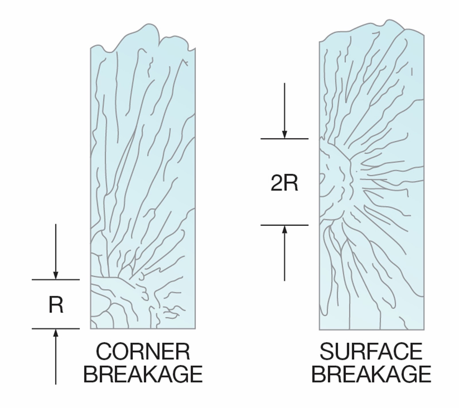
experience the differential expansion from  rapid heating, which can cause breaks. 

The previously fired piece will need a slower initial ramp rate this time. This is because you are firing for a sharp tack. This is also known as fusing to stick, or sintering. It is not because of a second firing. It is because of the differences in the glass for this firing. You are firing a single thicker piece of uneven layers to a sharp tack.

Looking at Stone* and the Bullseye chart for Annealing Thick Slabs indicates that in general, the first ramp rate should be halved for each doubling of calculated thickness. This is for full fused items. However, this is going to be a more difficult fusing profile - sintering. The calculation for sintering is as for 2.5 times the thickest part of the piece. This factor of 2.5 was determined by a series of experiments that are detailed in the eBook Low Temperature Kilnforming.

You started with firing two layers of 3mm/0.125” at possibly 330°C/595°F. You are now firing the fused 6mm/0.252 piece to a sharp tack. This means you should be looking at firing for 2.5 times or 15mm/0.625”. This implies 240°C/435°F as the maximum first ramp rate. A more cautious approach is to fire to 300ºC/540ºF at a rate of 72ºC/130ºF, as most heat-up breaks occur below that temperature. You should maintain that rate to 540°C/1005°F afterwards. 

Annealing

The annealing time and cool rate will be affected in the same way as the change to a sharp tack firing. Without that fuse profile change, and no change in the profile or thickness of the piece, it could have been annealed as previously. However, changing to a sharp tack means a longer anneal soak is required. This sharp tack annealing is for 2.5 times the thickness or 150 minutes.

Cooling

The cooling rates for this piece are not the same as for the first firing. A sharp tack firing will require cooling rates of:

  • 40ºC/73ºF to 482°C/900°F.
  • 72ºC/130ºF f427ºC/800ºF.
  • 240ºC/435ºF to room temperature

This applies regardless of the fusing glass you are using, as it is the viscosity which is the important factor in cooling.  Viscosity is primarily related to temperature.


Refiring with Significant Additions.

Ramp rate

If there are additions to the thickness, a slower first ramp rate will necessary. If an additional 3mm layer is placed on top of a 6mm base for a rounded tack, you will need to schedule as for 19mm/0.75” (twice the thickest part). This will be 150°C/270°F for the first ramp rate. For a sharp tack, it will be as for 22.5mm/0.825”. The maximum rate will be reduced to 120ºC/216F for the first ramp. This shows the additional caution required for sharper fusing profiles.

Annealing

The annealing will need to be longer than the first firing. The thickness has changed with the additions of pieces for a rounded tack firing. Instead of annealing for 6mm/0.25” you will be annealing as for 19mm/0.75”. This requires a hold of three hours at the annealing temperature and cooling over three stages:

  • The first cool rate is 25°C/45°F per hour to 482°C/900°F.
  • The second rate is 45°C/81°F per hour to 427ºC/800ºF.
  • The last rate is at 90C°C/162°F per hour to room temperature.

If there are additions, plus firing to the lowest possible tack temperature – as in the example - the firing must be as for 2.5 times the actual thickness. Annealing as for 25mm/1” gives rates of:

  • The first cool rate is 15°C/27°F per hour to 482°C/900°F.
  • The second rate is 27°C/49°F per hour to 427ºC/800ºF.
  • The last rate is at 90C°C/162°F per hour to room temperature.

These examples show how dramatically later additions in thickness can add to the length of the firing to re-fire a well-annealed piece without breaking it on the heat-up. It also shows that changing the profile to a sharper tack affects the annealing and cooling times and rates.


*Graham Stone. Firing Schedules for Glass; the Kiln Companion. 2000, Melbourne. ISBN 0-646-397733-8

As a side note Stone’s book has become a collectable.


Wednesday 21 February 2024

Go-to Schedules

 It’s a schedule I always use.

This is a frequent statement in response to a firing that has gone wrong.

You don't always fuse the same thing, or the same design, or the same thickness, etc. So why always use the same schedule?

The schedule for the firing each piece needs to be assessed individually. It may be similar to previous firings. But it may have differences. Assess what those differences mean for the firing.  Some factors to consider.

Addition of another layer to a stack in tack fusing makes a difference to the firing requirements. Even if it is only on part of the piece. It needs to have a slower ramp rate and a longer anneal soak and slower cooling.

A different design will make a difference in firing requirements too. For example, if you are adding a design to the edges of the glass, you will need different bubble squeeze schedules than when you do not have a border. It will need to be slower and longer than usual.

The placement of the piece in the kiln may require a re-think of the schedule too. If the piece is near the edge of the kiln shelf, or in a cool part of the kiln while others are more central, the same schedule is unlikely to work. You need to slow the schedule to account for the different heat work each piece will receive during the firing.

If you have introduced a strong contrast of colour or mixed transparent and opalescent glass in a different way, you may need slower heat ups and longer cools.

These are some examples of why the same schedule does not work all the time. It works for pieces that are the same. But it does not work for pieces that are different. And we should not expect it to.

There are sources to help in developing appropriate schedules. Bob Leatherbarrow’s book FiringSchedules for Kilnformed Glass is an excellent one.

Another one is especially good for lower temperature work: Low Temperature Kilnforming, anEvidence-Based Approach to Scheduling. Be aware that I have a vested interest here – I wrote it.


Wednesday 14 February 2024

Differential Cooling of Transparent and Opalescent Glass

A statement was made on a Facebook group that transparent glass absorbs more heat than opalescent glass. And it releases more heat during cooling. The poster may have meant that the transparent heats more quickly than the opalescent, and cools more quickly.

Yes, dark transparent glass absorbs heat quicker than most opalescent (marginally), and it releases the heat more quickly (again marginally) than opalescent. The colour and degree of transparency do not absorb any more or less heat, given appropriate rates. They gain the same heat and temperature, although at slightly different rates due to differences in viscosity.

An occasional table


The rate of heating and cooling is important in maintaining an equal rate of absorption of heat. The temperature of both styles can become the same if appropriate lengths of heating, annealing, and cooling are used. The slightly different rates of heat gain can give a difference in viscosity and therefore expansion.  This slight mismatch during rapid ramp rates, might set up stresses great enough to break the glass. This can occur on the quick heat up of glass during the brittle phase (approximately up to 540ºC/1005ºF). In fact, most heat-up breaks occur below 300ºC/540ºF.

The main impact of differential heat gain/loss is during cooling. Annealing of sufficient length eliminates the problem of differential contraction through achieving and maintaining the Delta T = 5C or less (ΔT≤5C). It is during the cooling that the rates of heat loss may have an effect. The marginally quicker heat loss of many transparents over most  opalescent glass exhibits different viscosities and rates of contraction. The stresses created are temporary. But they might be great enough to cause breaks during the cooling. Slow cooling related to the thickness and nature of the glass takes care of the differential contraction rates by maintaining small temperature differentials.

Significance of Differential Heat Gain/Loss

Uneven thicknesses and the tack fusing profile both have much greater effects than the differential cooling rates of transparent and opalescent glass. It may be that strongly contrasting colours (such as purple and white) are also more important factors in heat gain and loss than transparent and opalescent combinations.  Cooling at an appropriate rate to room temperature for these factors will be sufficient to remove any risk of differential contraction between transparent and opalescent glasses.

Wednesday 7 February 2024

Comparison of Citric Acid and Trisodium Citrate.

These two substances are useful means of removing kiln wash and refractory mould material from glass. They are important where abrasive methods such as sand blasting are not available or appropriate.

My recent experience with both citric acid and trisodium citrate shows differences in performance. This makes each more suitable in different contexts.

credit: Amazon


Trisodium citrate is the safest option when long soaks are required to remove refractory mould material. The trisodium citrate removes any risk of etching the glass on long soaks. It has been shown by Christopher Jeffree that two-day soaks in this will not etch the glass. It is most suitable for casting work.


Items cleaned with citric acid and vinegar
credit: Christopher Jeffree

Citric acid acts quickly on kiln wash, making long soaks less necessary. Depending on the thickness of the stuck kiln wash and the amount of agitation of the stuck kiln wash, the time required may be only a dozen minutes. It rarely takes more than a few hours.  Citric acid does not work quickly on refractory materials. This makes the trisodium citrate the better choice for long soaks.

 More on citric acid as a cleaner

 More on citric acid

More on trisodium citrate

Wednesday 31 January 2024

Care of Ceramic Kiln Shelves

Mullite kiln shelves
credit: IPS Ceramics


The most popular and easily available ceramic shelves are made from Mullite, Cordierite, and CoreLite. Other hard specialist kiln shelves are available. They are made of other materials. Shelves are also made from other materials such as refractory fibre board, vermiculite, and fire-resistant ceiling tiles. This concentrates on the care of ceramic shelves.

Composition and Characteristics

This table gives some information about the characteristics of the materials involved in these shelves.


Name

Thermal Shock Resistance

Brittle

Strength

Composition

CoreLite

Low

Yes

Moderate

Ceramic with a high silica content

Cordierite

High

Yes

Strong, but heavy

Magnesium, iron, aluminium oxide, silica

Mullite

High

Yes

Strong. but heavy

Silica, Aluminium oxide


CoreLite is a trade name for an extruded ceramic shelf. It is strong, but brittle. It is subject to thermal shock below 540ºC/1000ºF. This suggests the ceramic has a high silica content as the quartz inversion is at 573°C/1063°F, where the ceramic has a sudden expansion on heating and an equal contraction on cooling. The cooling rate at this temperature is normally slow enough to avoid breakage.

credit: Clay Planet


cordierite - composed of magnesium, iron, aluminium oxide, and silica. hard, brittle, and with low expansion characteristics.

credit: refractorykilnfurniture.com


Mullitecomposed largely of silica and aluminium oxide. It is strong, brittle, and has good thermal shock resistance.

Care

There is enough information from considering the composition of these shelves to indicate they are all brittle and have differing vulnerabilities. These have implications for storage, use and cleaning.

Storage

If storing vertically, take care to avoid setting down on hard surfaces. If they are in a rack, have a separate slot for each shelf. This avoids friction between shelves and possible surface scratches. The most useful material for these racks is wood, or harder materials covered with wood. These racks can be horizontal or vertical.

If it is not possible to have a separate rack for each shelf, do not lean them on each other. Shelves leaning against others or against hard surfaces can become scratched. Provide a cushion against scratches such as cardboard, or thin plywood.

When moving the shelves, avoid setting them down on their corners, or bumping the shelf anywhere against hard structures.

Use

Reduce firing speeds to less than 220ºC/430ºF per hour up to 540ºC/1005ºF, especially for CoreLite shelves. Cordierite and Mullite shelves are not as sensitive, but still can be broken by fast firing rates in this temperature region.

Cover a large portion of the shelf at each firing to avoid uneven heating of the shelf. It is best to evenly distribute moulds and other things that shade the heat from the shelf around the shelf to help avoid thermal shock breaks.

If you cannot or do not want to cover the whole shelf, elevate the mould(s). This helps to keep the whole shelf at the same temperature when only small parts of shelf are covered. It does not seem to matter so much when flat glass is in contact with the shelf. But continue to observe the moderate ramp rates below 540ºC/1005ºF.

It is even more important to elevate damp or heavy moulds from the shelf. These kinds of moulds shade the heat from the shelf immediately below them while the rest of the shelf heats rapidly. This difference in expansion over parts of the shelf becomes too great for the shelf to resist.

Another thing to avoid is cutting fibre or shelf paper on top of the shelf. It often creates long shallow scratches in the shelf. These can be the source of bubbles, but more often, flaws on the back of the fired pieces.

Cleaning

Care is needed to avoid mechanical damage during cleaning. Scraping can create scratches in the shelf. These are difficult to remove or fill smoothly. So, scraping needs to be done carefully.

Any sanding also needs to be done carefully. If you use power tools, it is very easy to create shallow depressions that will be the source of bubbles in future firings. It is slightly more time consuming to manually sand the kiln wash with a sanding screen with or without a holder. But it preserves the flatness of the surface.

If it is decided to wash the shelf primer off the shelf, consider how difficult it is to wash a very persistent baked on substance. It requires thorough scrubbing to remove all the hardened material. Power washers are not advised since the high water pressure can abrade the surface of the shelf.  But if you do decide on washing, you need to air dry for several days afterwards. Then kiln dry slowly to just below boiling point of water. Soak at that point for several hours, or until a mirror held above the open port does not fog up.

There is more information on removing kiln wash here and here.


Summary

Ceramic kiln shelves are hard, but subject to scratches, impact breaks, excess dampness, failure due to uneven temperatures, and to rapid rises in temperature below 540ºC/1005ºF.

Wednesday 24 January 2024

Thickness of Powder Application


Why does my powder disappear when I fire?


Powder may appear to disappear after firing as Donna Brown found out with the pieces of her work shown here. Glass powder is finely ground glass sheet. The full colour of glass sheet is seen only when the glass is 3mm thick. So, to get the same intensity of colour you need to have the powder nearly 3mm thick.

This image shows the powder application before firing.
Picture credit: Donna Brown

There is not enough powder applied to the honeycomb. Everyone needs to run some tests to see how much powder is needed for strong colour. By running some tests of different thicknesses of powder you will be able to see how shading effects can be produced with powder. You should run the tests on both light coloured and dark coloured bases. Opalescent glass requires more powder than transparent. Opaque powders are better than transparent colours to show on dark colour.


This image shows the result of the firing, showing a thicker application of powder was required to give the full effect.
Picture credit: Donna Brown


In this particular application, I would put the powdered colour down and then the honeycomb grid on top for better definition of the honeycomb.


Fading powders  

Colour dilution   

Wednesday 17 January 2024

Mending a crack

 I had a piece crack due to an annealing oops. I put powder on it and put it back in at a higher temp with a much longer anneal time. It looks great on the front, but I can still see where the crack was on the back. Is it supposed to be like that? I didn't think to put powder on that side.

If you think about why you get crisp lines at the bottom of a strip construction and a more fluid appearance on the top, you will be near the answer of why a repair looks ok on top but shows the crack on the bottom. The temperature on the bottom of the glass is less than on the top at the working temperature. And less again than the air temperature which we measure. This means that the bottom part of the glass has less chance to fully recombine. This, combined with the resistance to movement of the glass along the shelf, results in evidence of the crack being maintained.

Credit: Clearwater Glass Studio


There are some things that can be done to minimise the evidence of the crack. Make sure you know why your piece cracked before you try to mend it. An annealing crack will need different treatment than a thermal shock crack or a compatibility crack. Simply refiring the piece may only make the problem worse.

One approach is to place a sheet underneath. Make sure the broken glass is well cleaned and firmly pushed together. Dams may be useful to keep the glass compressed together. Glass expands both horizontally and vertically during the fusing process. Confining the glass will transfer most of the expansion in a vertical direction. This additional (small) vertical movement may help in forming the glass seamlessly. The broken glass now being supported by an unbroken sheet will enable the movement required to “heal” the crack.


If you do not want to change the surface, you can fire upside down. To do this you need to have a loose bed of powdered kiln wash, or whiting (a form of chalk) that is thick enough to press the textured side fully into the separator. Make sure the glass is pressed together without any separator getting into the crack. One way to ensure the crack does not open is to use a small amount of cyanoacrylate (super) glue which will burn away during the firing.  Put a sheet of clear glass over and fire. Thoroughly clean the face after this repair firing. The ultimate top needs to be fire polished to remove the evidence of the crack, and if it has picked up any marks from the powder.

You could, of course, fire upside down in this way but without the additional sheet, to avoid making the piece any thicker. This may or may not work well. If the base layer is one layer thick, it may pull in at the sides and pull apart at the crack where it is one layer thick.  It is also possible that bubbles will develop in the thin parts of tack glass because of the uneven thicknesses.

A final note. Placing powder on the back will not improve things. The powder will not fully incorporate with the glass and so leave a rough surface without concealing the crack.

Avoiding breaks

To repair or not

The process of repairing

Wednesday 10 January 2024

Identification of Mechanical and Thermal Stress

The Identification of stress is important in investigating the causes of stress. We have well established clues to help us with our glass selection and alteration of our firing schedules. We can get more information about why the cold glass has broken from the scientific literature. The manufacturers of float glass and the installers of large panes investigate thoroughly the causes of breaks in glass that has been installed. 

One article - Breaking It Down, Why Did the Glass Break? by Timothy Bellovary from Vitro Architectural Glass - looks at mechanical and thermal stress and distinguishing between the two.  This post is quoted extracts from that article. [Text in square brackets are interpolations of mine].   Note that all the illustrations are from the article and are copyrighted.

Source: https://vcn.vitroglazings.com/technical-forumdiagnosing-glass-breakage

Identifying the break origin can provide hints about the following:

·         Mode of glass failure—Was it mechanical or thermally induced stress?

·         The stress or tension level at which the breakage occurred.

·         Other contributing factors—were there digs (deep, short scratches) resulting from glass-to-glass or glass-to-metal contact? Did a projectile hit the glass? Is there edge or surface damage?


To find the origin of a break, the first step is to assess its direction by inspecting the fracture lines… in the glass. These rib-shaped marks, distinguished by a wave-like pattern, begin at the break origin and radiate along break branches, and almost always project into the concave face of these lines.


Figure 1
Diagram of Fracture Line Direction


It’s often helpful to make a basic diagram (see Figure 1) of the fracture lines. … The origin of the break can be determined by:

·         Drawing arrows (indicating fracture line direction) pointing into the concave face of break wave markings in the glass edge.

·         Tracing point-to-tail of arrows back to the break origin.


Mechanical Stress

Low-stress tension breaks are experienced most frequently by residential window and IGU manufacturers. The origin of the break is typically at damaged areas of the edge or surfaces near the edge, such as digs, scratches or chips. In many cases, breakage from damaged glass occurs after the initial edge damage is incurred, such as during IGU fabrication, sashing operations, transportation, job-site handling or storage, or the installation process.

In Figure 2, the break origin is not 90 degrees to the edge of the glass, indicating a tension break caused by bending. Low-stress, mechanical tension breaks often occur from bending at less than 1,500 psi.

Figure 2

Low-Stress Mechanical Tension Break


High-stress tension breaks share one characteristic with low-stress tension breaks: The break origin is not 90 degrees to the edge of the glass, suggesting a tension break caused by bending. However, additional branching of the crack within two inches of the break origin (see Figure 3) indicates that the stress at breakage was likely higher than 1,500 psi.


Figure 3

High-Stress Mechanical Tension Break


Thermal Stress

Thermal stress breaks often originate at the edge of the glass and form virtually 90-degree angles to the edge and surface of the glass.

As with mechanical stress, there are two types of thermal stress breaks: low stress and high stress.


Figure 4

Low-Stress Thermal Break

Low-stress thermal breaks are often indicated by a single break line starting at the break origin point at or near the glass edge and propagating two inches or more before branching into more break lines (see Figure 4). Damaged glass edges are the most frequent cause of low-stress thermal breakage.


High-stress thermal breaks appear as a single break line starting at the break origin point at or near the glass edge and generally branching into additional breaks within two inches [50mm] of the origin. This indicates a breakage brought on by conditions that cause high thermal stress, such as severe outdoor shading on parts of the glazing; heating registers located between the glass and indoor shading devices; closed, light-colored drapes located close to the glass; or glazing in massive concrete, stone or similar framing.


Figure 5

High-Stress Thermal Break

Analysing the Break Origin

A reliable method for estimating the stress level of a break at failure is a mirror radius measurement. Radius dimensions are determined by crack propagation velocity characteristics.

A crack propagates itself through glass with increasing velocity as it moves further from the point of origin. If an object has sufficient energy to propagate a crack through the thickness of the glass, then a “spider web” pattern will form. ….

Near the point of origin, a smooth, mirror-like appearance on the fracture face indicates a low crack velocity. However, as velocity increases (due to higher tension stress), the fracture face takes on a frosted look; then, at the highest velocity, it assumes a ragged or hackled appearance. Mirror radii appear in various forms, depending on the stress level of the fracture.

Figure 6 shows break origins resulting from high tensile stresses, such as bending or thermal stress breaks.

Figure 6

High-Stress Mirror Radii
(R = Mirror radii)


Figure 7 represents the break origins of glass fracturing at low bending stresses. In this example, a smooth fracture face forms across the thickness of the substrate. When the breaking stress is low, the mirror radius is often radial and may extend deeply into the substrate.

Figure 7

Low-Stress Mirror Radii
(R = Mirror radii)


To identify what damaged the glass in the first place, four factors are examined during this analysis:

·         Impact

·         Inclusions

·         Thermal variance

·         Pressure differentials

Impact

Identifying the nature of the breakage pattern can determine whether a foreign object hit the glass and whether the impact was perpendicular or parallel.

Depending on the severity of the impact, the immediate area surrounding the break origin might be cracked, crushed or missing.

                 
Figure 9

High-Stress Mechanical Breakage

[This pattern of break is often exhibited when the separator fails or is insufficient to keep the glass from sticking to the ceramic support shelf.] …

Inclusions

Any undesirable material embedded in glass is considered an inclusion. ... [In general, kilnformers place inclusions within the glass and know the risks of breaks].

Thermal Variance

[This article relates to float glass installations, but the principle remains.] If the temperature difference across a [piece] of glass is great enough, the accompanying stresses can reach levels that cause breakage. … The combination of contact, surface damage and localized temperature gradients can greatly increase the likelihood of breakage.

Pressure Differentials

[This section applies mainly to Insulated Glazing Units. It points out that differences in altitude between the manufacturing and installation sites – in combination with temperature – can cause breaks. It is not of primary importance to most kilnforming, but something which should be considered when installing kilnformed glass in an IGU]

Conclusion

[Occasionally] glass breaks for no obvious reason. Whether it’s a one-off or part of a continuing pattern of incidents, glass breakage is inconvenient, potentially dangerous and costly. … Conducting “post-mortems” on glass breaks helps investigators identify the general reasons for each incident, including the type of failure that caused the break, and the potential original source of the damage. By using the techniques outlined in this article, [kilnformers] may be able to accurately identify the likely origin of such failures and … use that information to prevent future occurrences.

https://vcn.vitroglazings.com/technical-forumdiagnosing-glass-breakage

[An important element in identifying breaks in kilnforming that this article demonstrates is the difference in the angle of the break. A 90 degree angle to the surface indicates a thermal cause to the break. The more branching of the lines of breakage, the greater the stress. The branching breaks indicate there was significant temperature difference.

The breaks which are less than a right angle to the surface indicate a mechanical origin of the stress. This is usually the glass breaking at a weak point when subject to a bending stress.

If the point of origin of the stress can be identified as demonstrated in the article, it may help in determining causes. One of these causes might be hot or cold spots in the kiln.]


Wednesday 3 January 2024

Stainless Steel Stringer Pots

Credit: Paul Gardner httpswww.facebook.com


 It is a consideration in stringer and murrini work that the pot be re-usable. This has led to the development of stainless steel square pots.  The thorough cleaning of these is difficult even with a lot of banging. Containers with removal bases have been developed as a result.

 The importance of a container with an integrated bottom is to ensure the glass is contained within the pot. To be reusable, the pot can be lined with fibre on sides and bottom. However, fibres can be drawn from the lining into the stream of glass.

Credit: Paul Gardner

 If you have a stainless-steel square with a removable bottom, the pot can be cleaned more easily and does not need the fibre lining. It also allows easy switching of bases with different hole sizes and shapes.

 However, some people have had the difficulty of the glass flowing out between the sides and bottom of the pot and onto the floor of the kiln. Glass is heavy and can float the much lighter stainless steel off the base, allowing the glass to flow sideways as well as through the hole in the base.

 This indicates that the stainless steel square should be weighted down. Placing kiln furniture on top of the pot can avoid it being floated off the base piece. These can be dams made from kiln shelves, dense fire brick, a small shelf, ceramic tiles, or other kiln furniture. Putting the furniture on two opposing corners will be enough to counteract the floating of the pot and still allow radiant heat to reach the glass.

Pots can be made from refractory materials too, such as vermiculite.

Liners for pots

Wednesday 27 December 2023

Scheduling with the Bullseye Annealing Chart

This post is about adapting the Bullseye chart Annealing Thick Slabs to write a schedule for any soda lime glass as used in kilnforming.

I frequently recommend that people should use the Bullseye chart for Annealing Thick Slabs in Celsius  and Fahrenheit.  This chart applies to glass from 6mm to 200mm (0.25” to 8”).

“Why should the Bullseye annealing chart be used instead of some other source?  I don’t use Bullseye.”

My answer is that the information in the chart is the most thoroughly researched set of tables for fusing compatible glass that is currently available.  This means that the soak times and rates for the thicknesses can be relied upon.

“How can it be used for glass other than Bullseye?”  

The rates and times given in the chart work for any soda lime glass, even float. It is only some of the temperatures that need to be changed.

"How do I do that?"  

My usual response is: substitute the annealing temperature for your glass into the one given in the Bullseye table.

 "It’s only half a schedule."

That is so.  The heating of glass is so dependent on layup, size, style, process, and purpose of the piece.  This makes it exceedingly difficult to suggest a generally applicable firing schedule.  People find this out after using already set schedules for a while. What works for one layup does not for another.

Devising a Schedule for the Heat Up

There is no recommendation from the chart on heat up.  You have to write your own schedule for the first ramps.  I can give some general advice on some of the things you need to be aware of while composing your schedule.

The essential element to note is that the Bullseye chart is based on evenly thick pieces of glass.  Tack fusing different thicknesses of glass across the piece, requires more caution. The practical process is to fire as for thicker pieces.  The amount of additional thickness is determined by the profile being used.  The calculation for addition depends on the final profile.  The calculation for thickness is as follows:

  • Contour fusing - multiply the thickest part by 1.5. 
  • Tack fusing - multiply the thickest part by 2. 
  • Sharp tack or sinter - multiply the thickest part by 2.5.

The end cooling rate for the appropriate thickness is a guide for the first ramp rate of your schedule.  For example, the final rate for an evenly thick piece 19mm/0.75” is 150ºC/270ºF.  This could be used as the rate for the first ramp. 

Bob Leatherbarrow has noted that most breaks occur below 260ºC/500ºF.  If there are multiple concerns, more caution can be used for the starting ramp rate.  My testing shows that using a rate of two thirds the final rate of cooling with a 20 minute soak is cautious.  In this example of a 19mm piece it would be 100ºC/180ºF per hour.

Even though for thinner pieces the rates given are much faster, be careful.  It is not advisable to raise the temperature faster than 330ºC/600ºF per hour to care for both the glass and the kiln shelf.

Once the soak at 260ºC//500ºF is finished, the ramp to the bubble squeeze should maintain the previous rate.  It should not be speeded up.  The glass is still in the brittle phase.

After the bubble squeeze you can use a ramp rate to the top temperature of up to 330C/600F.   AFAP rates to top temperature are not advisable.  It is difficult to maintain control of the overshoots in temperature that are created by rapid rates.  

The top temperature should be such as to achieve the result in 10 minutes to avoid problems that can occur with extended soaks at top temperature.

In the example of an evenly thick 19mm/0.75” piece a heat up full fuse schedule like this could be used:

  • 150ºC/270ºF to 566ºC/1052ºF for 0 minutes
  • 50C/90F to 643C/1191F for 30 minutes
  • 333ºC/600ºF to 804ºC/1479ºF for 10 minutes


If a more cautious approach to the heat up is desired, this might be the kind of schedule used:


  • 100ºC/180ºF to 260ºC/500ºF for 20 minutes
  • 100ºC/180ºF to 566ºC/1052ºF for 0 minutes
  • 50C/90F to 643ºC/1191ºF for 30 minutes
  • 333ºC/600ºF to 804ºC/1479ºF for 10 minutes

This approach is applicable to all fusing glasses.


Adapting the Bullseye Annealing Chart

After writing the first part of the schedule, you can continue to apply the annealing information from the Bullseye chart.  The first part of the anneal cooling starts with dropping the temperature as fast as possible to the annealing temperature.

The method for making the chart applicable to the annealing is a matter of substitution of temperatures.  

First, determine the annealing point of the glass.  Go to the web page of the glass manufacturer to get their annealing temperature.  You can use the information in this blog post giving some of the critical temperatures for a range of glasses.  This information has been taken from the manufacturers’ web sites as they are sometimes difficult to find.  A brief listing of some published annealing soak temperatures:

  • Bullseye                               482C/900F
  • Oceanside                            510C/960F
  • Uroboros by Youghiogheny     510C/960F
  • Old Uroboros                        519C/967F
  • Wissmach 96                        482C/900F
  • Youghiogheny96                    510C/960F
  • Float Glass
  • Pilkington Optiwhite               559C/1039F
  • Pilkington Optifloat                548C/1019F
  • USA float (typical)                 548C/1019F
  • Australian float (typical)         548C/1019F

Use the annealing temperature from your source as the target temperature in place of the Bullseye temperature.

The annealing soak times are important to equalise the temperature within the glass to an acceptable level (ΔT=5ºC).  The annealing soak time is related to the calculated thickness of the piece.  This measurement is done in the same way as devising the appropriate rate for heat up. 

Applying the Cooing Rates

Then apply the rates and temperatures as given in the chart.  The three stage cooling is important.  The gradually increasing rates keep the temperature differentials within acceptable bounds with the most rapid and safe rates.

The temperatures and rates remain the same for all soda lime glasses – the range of glass currently used in fusing, including float glass.  The soak time for the calculated thickness of your glass piece will be the same as in the Bullseye chart.  

This means that the first cooling stage will be to 427ºC/800ºF.  The second stage will be from 427ºC/800ºF to 371ºC/700˚F.  And the final stage will be from 371ºC/700˚F to room temperature.

I will repeat, because it is so important, that the thickness to be used for the anneal soak and cooling rates for your schedule relates to the profile you desire.  A fuse with even thickness across the whole piece can use the times, temperatures, and rates as given in the chart as adapted for your glass.  The thicknesses to use are for:

Contour fusing - multiply the thickest part by 1.5. 

Tack fusing - multiply the thickest part by 2. 

Sharp tack or sinter - multiply the thickest part by 2.5.

An annealing cool schedule for 19mm/0.75" Oceanside glass is like this:

  • AFAP to 510˚C/ 951˚F for 3:00 hours
  • 25˚C/45˚F to 427˚C/800˚F for 0 time
  • 45˚C/81˚F to 371˚C/700˚F for 0 time
  • 150˚C/270˚F to room temperature, off.


Many will wish to turn off the kiln as early as possible.  This is not part of best kilnforming practice.  If you still wish to do this, the turn off temperature must be related to the thickness and nature of the piece.  To turn off safely, you need to know the cooling characteristics of your kiln.  This can be determined by observing the temperature against time and then calculating the kiln’s natural cooling rateAnd then applying that information to cooling the kiln.


The best source for devising schedules is the Bullseye chart for Annealing Thick Slabs.  It is well researched and is applicable with little work to develop appropriate schedules for all the fusing glasses currently in use.