Thursday 5 January 2012

Paper

The traditional approach to cartoons meant three versions were necessary. One with all the drawing details, one with the cut lines, and one for layout and leading.

If you are doing a leaded or copper foiled panel without details for painting on glass two copies are the maximum required. I make do with one original, as I have no place to keep the glass pieces laid out while cutting and beginning to lead, nor do I make templates for cutting.

The paper you need is one that is stiff enough to avoid changes in shape or wrinkling with changes in humidity. The paper also has to be robust enough to stand up to lots of movement. Cartridge paper from a roll works well, but is often seen as expensive. Brown wrapping paper is usually stiff enough, although thinner than cartridge paper.

Tracing paper is very useful, if you do not have a light box, as you can trace details from one version of a cartoon – whether new or from an old one – into another. However it changes shape when exposed to high humidity. To transfer the cartoon to more stable or more opaque paper, you can use a pounce wheel to transfer through the tracing paper for the final cartoon.
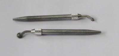
Two pounce wheels

If you have a light box you can use it to make the transfer, or you can stand at a window with the two sheets of paper taped together to trace the design onto the final cartoon paper.

If you need to make pattern pieces you will need a second copy to cut up. Here you need paper or card that lies flat. You may also find it useful to cover the main cartoon with a water proof covering if you are going to do a lot of grinding and fitting over the cartoon. You can do this by oiling your paper (as for stencils) or by sticking clear vinyl over the cartoon.

Friday 30 December 2011

Soldering Radiating Lines

Some times no matter how you try to avoid it in the design, you end up with multiple solder lines joining at one point.

In copper foil work, I find it best to tin all the copper foil before assembly, as this means you can use a minimum of solder to tack solder the pieces to one another.

You will be left with less solder at the joint if you start from the joint and move away from it while soldering. This drags the solder into the bead line rather than letting the solder build up at the joint of the multiple lines and give a resulting high point resulting from the accumulation of solder there.


Monday 26 December 2011

Kiln Furniture

You do not have to buy all your kiln furniture. Any refractory material – any heat resistant material that will stand up to the forming temperatures – that you have from broken shelves or used material will do.
The advantage to home made kiln furniture is that you can have exactly the shape you want. There are a number of possibilities.


Example of broken shelves

 Broken kiln shelves can provide supports and dams. They can be cut with a tile saw to give long strips that can be used as dams. Smaller squares and rectangles can be stacked to give height to other supports for the glass.

Cutting a shelf with a hand saw
25mm vermiculite board

Vermiculite in the form of a pressed board provides a medium strength kiln furniture. It can be cut with a wood saw, although it dulls cutting tools quickly. The board can also be carved with wood working tools although it is very abrasive, requiring tools to be sharpened before use on wood again.

25mm ceramic fibre board

Fibre board is not as strong or rigid as kiln shelves and vermiculite are, but is much more adaptable to curves and undulations. They can be cut with a knife and used with or without hardener – colloidal silica. If the hardener is used some kind of separator will be required to keep the glass from sticking. Dust masks are required for working with ceramic fibres.


Soft fire brick

Soft fire brick can be cut with a hand saw into many shapes and and sizes. They are suitable as supports and braces for dams.  There are also higher density bricks that are much heavier to resist the movement of dams.


3mm fibre paper

Fibre paper can be cut and stacked to provide shims to level shelves and moulds. Shapes can be cut into stacked layers of the material to provide dams for irregular shaped projects.

Thursday 15 December 2011

Uneven Slumps

Uneven slumps are an occasional feature of kiln forming. There are a number of possibilities that can cause this.
A mould that is not level will lead to an asymmetrical slump. You need to make sure on each firing that the mould is level, as well as your kiln and the shelf or supports. A three-way level can check this quickly.
Glass that is placed unevenly on the mould can cause uneven slumps. The glass should be placed on the mould so that it is equidistant from the edges of the mould all the way around. The glass needs to be level too. Again the three way level can help.

A slight bevel on the bottom edge can help avoid any catching of the glass as it moves within the mould.
Baffling or shielding parts of the glass can keep the heat off areas that tend to heat up faster than the rest and so begin moving before other parts of the blank.

Deep moulds most often present difficulties with uneven slumping. The best approach here is to use multiple, progressively deep slumps.

It also is possible to reach in with a wet stick and move the glass back to an even slump during the firing. Please observe all the safety requirements.

Most importantly, slow temperature rises solve most of the problems of uneven slumps. Fast temperature rises allow the component parts of the piece to absorb heat differently for different colours and glass of different viscosities. Slow rises in temperature help avoid any unevenness in the way the kiln heats the piece. Slow rises give more control and achieve the result at a lower temperature.

Note that a number of the solutions require observation while firing. The best results come from observing what is happening in the kiln. It allows you to make corrections either while firing, or – more often – in the next firing of a similar project.


Saturday 10 December 2011

Leaking Cutters


People sometimes comment that their cutters are leaking. Most cutters of the pencil type are not prone to leaking. Some of the pistol shaped cutters seem to have more difficulty.
One possibility is that the oil being used is too thin for the system that dispenses the oil. In that case a little thicker oil may cure the problem.

It may be that the oil is leaking from some where else than the valve or wick that is intended to dispense the oil. This sometimes happens when excessive pressure has been put on plastic handled cutters whether pencil or pistol. In this case, the alternative is to replace the cutter or use another method.

The other method could be called the dip and cut method. In this case you leave the reservoir empty and have a shallow container filled with oil soaked cotton wool. Dip the cutter wheel into the cotton wool before each cut and this will give you enough lubrication for the score. A variation on this is to dip a brush in a container of oil or turpentine substitute and paint along the line of the cut before scoring. Both are effective.

Although it is not a repair, you can push a cotton wool lump down to the valve or wick, saturate it with oil and then there is enough oil to lubricate the cutter wheel, without an excess to leak out. You do need to renew the oil for the lump of cotton wool from time to time.

Monday 5 December 2011

Reworking Designs

Principles of design practice for stained glass, 5

Having created the design, you should consider re-working the designs for a variety of reasons. Some of these are:

- to save time in the later stages of the work. It all too easy in the excitement of creating a new piece to want to get directly on with making, however this often gives construction or design difficulties that have to be solved in the making, leading to compromises. In general far too little time is spent in the design stage. Time spent on the design will be more than saved in the construction and will produce a more satisfactory piece.

- to ensure the structural stability of the piece. Although reinforcement should be considered from the beginning of the design, this is the time to ensure that the piece will stand up to the use it will receive during its – expected – long life.

- Make sure you have investigated every possibility to answer the challenges of your design.

There are a number of activities that can help with these elements.

Reworking will enable you to maintain the essence of the design while simplifying lines and easing the labour of the construction of the panel. Often the design contains a number of lines that are not essential to the whole design.

As you re-work the design, you can make sure every curve, dip and angle are to your liking and so improve the whole. Redrawing also helps understanding of the design and the placing of lines. It will also help in considering the placement of lead came and the widths to be used.

Make sure the design is still structurally sound. The design should avoid long nearly straight lines with few interruptions, especially those that go from edge to edge in any direction. The lines should interlock rather than have many joins onto long lines.

It gives an opportunity to ensure that you can cut all the pieces. This is the time to look at the negative or background pieces to make sure you can cut them as well as the foreground pieces. Usually people are so concentrated on designing the main image that the background becomes too complicated to cut easily.

Make successive tracings with each change, so there is a record, allowing you to step back wards to an earlier version if necessary.

If this re-working stage leads to the realisation of design problems, there are some things that can be tried:
  • Cropping the design can transform it. The focus of the design can be enhanced by removing some of the surrounding “information”. The change of proportions say from landscape to portrait can make significant differences.
  • Enlarging and using only a portion of the original design can be a solution. This is similar to the cropping operation, but has the added advantage of making the pieces larger and easier to cut.
  • Further simplification of background design lines can be considered. This will bring the focus back onto the main part of the image.
  • Changing relative proportions can transform the design, e.g., by enlarging a busy background, it can be made simpler and easier to read the whole panel.
Elements of Design:

Wednesday 30 November 2011

Design Sources

Principles of design practice for stained glass, 4

Use the everyday visual experience and make interpretations and adaptations. E.g.,
  • draw lead lines on an illustration to make it suitable for stained glass, using the fewest lines possible
  • Use your photographs of interesting subjects and scenes
These may never become useable designs or cartoons, but will increase you abilities to design from the real world toward the abstract.

Make and keep sketches as personal references. These do not need to be finished drawings, just a reminder of the thing(s) that caught your eye. Many artists always carry around a notebook to record these observations. Even if you only make drawings on paper napkins, make a folder to keep these separate sketches together.

Take photos of shapes and interesting images. These can then be used later to develop images.

Make up composite images by using overlays or collage. This helps develop your compositional abilities.

Work on abstraction in your design practice:
  • Study abstract representations. Dissect – decomposition is a popular word - and analyse how the work is put together.
  • Use geometric design as an introduction to abstract design. This forces your attention to structure, balance and colour.
  • Once the distribution of the physical and visual weights is understood, this enables the jump to more free forms of abstraction.

Friday 25 November 2011

Beautiful Design Lines

Principles of design practice for stained glass, 3

Stained glass is a graphic medium where line and colour are very important. Achieving pleasing lines and forms requires practice and use of various approaches and techniques.

The two dimensional world is one of abstract thought. Work and development are the way to creativity – there is no mystical talent. Practice drawing every day – set aside time to do it, if you normally shy away from drawing as an exercise.

Study and learn from what has gone before. Look at the images and objects you admire and analyse what you like about them and why. Also consider what things could have been done differently. Consider how those changes would affect the character of the piece.

Of course, maintaining your creative attention is difficult, so when blocks occur try some or all of these things:
  • Put the work aside for a day or two before taking it out and looking at it again.
  • Alternatively, pin up the design on a wall where you can look at as you pass by. When you see a change to be made, do it immediately and pin it back up.
  • Get a new perspective, e.g.:
    • Turn it upside down. This will enable you to observe differences and spot inconsistencies
    • Look at it in a mirror. You might see people studying still life or live subjects together with their drawing in a hand mirror to get a new perspective that will help spot difficulties.
    • Put the design on the floor and climb a ladder to look at it. This provides distance and changes the angle at which you look at your design.

Remember that design tends toward realism or abstraction. You need to work on both forms, remembering that glass is a graphic medium that tends toward abstraction. Working on both forms develops your flexibility and knowledge. Having a working knowledge of both enables you to have a responsive approach to the client.

Sunday 20 November 2011

Responsive Colour Selection

Principles of design practice for stained glass, 2

The graphic form of much stained glass means that the medium is about line and colour. This requires that you think about both your and the viewer's response to the colour combinations. Respond to your instincts. Use you feelings about colour and their relationships. Try different colour ways. Formal training does help, but experience develops your skills. The individuality of the piece depends on the use of your instincts about the colour. There are some checks you can make while selecting colours.

Think of colour and impact. Hot colours tend to have more impact, as they give bright points or areas. Impact can also be created by using non-complementary colours together. If a more subtle impression is desired, use tonal variations without great contrasts.

Vary areas of colour and their proportions. This provides interest to a panel. It avoids a mechanical symmetrical appearance, even if the design is symmetrical

Think about colour balance. Although the colours may vary it is important that the weights of the colours are balanced so that the focus of the panel is not taken to another part because of the imbalance of the colour with the design.

When you are in difficulty selecting or arranging the colour, step back and view from a distance. This is one of several techniques to enable you to get a larger or different view. Others include viewing the design through a mirror, viewing through half closed eyes, look at the design from the other end, and viewing the design from acute angles.

When something feels wrong, trust your intuition and use other colours. Colour theory is just that -theory. It is through using your reactions that the piece becomes individual.

Seek out the nuances of the glass in tones and textures. These alter the perceived colour and weight considerably.

Keep the design lines simple when your emphasis is on colour, light and texture. This allows those qualities to dominate the panel, rather than the lines.

Always make a coloured drawing, before choosing the glass, as a reference. This is a rendering of your original idea. It provides a reference as you select the colours. It is something that can be altered, of course, but does provide an essential reference point.

Choose glass colours in the kind of light for which the panel is intended. This is essential, as the glass colour is subtly different in daylight, incandescent, and fluorescent lights.


Elements of Design:

Tuesday 15 November 2011

Designing for Strength

Principles of Design Practice for Stained Glass, 1

There comes a stage when each of us moves from using patterns developed by others to trying to realise our own vision. This is the time where in attempting to reproduce an image from our mind or from natural and man-made forms that we begin to encounter difficulties with the medium of glass and lead or copper foil.

There are a number of principles that should be kept in mind while designing, or at least referred to when the design is reaching its final stages. This series of notes is an attempt to outline a number of the most important points in designing glass panels, especially larger ones.
Structural strength
The panel needs to be strong to last for a long time. Glass is a very resilient material; so is lead and solder. It would be a shame to design a panel in long-lasting materials that will not last because of the design and construction. There are some things to remember about creating a strong panel.

The strength of a panel is in its glass.

Glass in compression is stronger than steel. It is only when it is in tension that its weakness - or fragility – becomes apparent. So the structural arrangement of the glass needs to be such that each piece of glass supports its neighbours. It also needs to use shapes that are strong.

Avoid the following shapes:
  • Hour glass shapes – those where the ends are wider/larger than the middle - will crack at the narrowest part. If the shape – usually a negative or background one – is necessary, break it up into smaller pieces that make sense in the whole design. It is also possible to add details that will break up these shapes, but be careful that the details do not detract from the whole.
  • Exaggerated, deep inner curves will crack at apex of curve. If unavoidable, you should consider adding design lines where the glass would break anyway, or moving elements closer together so they almost touch to avoid the single deep inner curve.
  • Thin long and tapering glass pieces will crack at the point or be covered by the lead or copper foil. Where you need to have such shapes, try drawing the lead or copper foil lines on the design. You can do this on a piece of tracing paper to avoid messing up your original design. This will show you how the finished panel may look. Alternatively, you can divide the long tapering piece of glass into several pieces so that any flexibility of the whole panel does not break the long thin piece. Short thin pieces are not so likely to be broken by any movement of the panel.

Lines radiating from a single point provide weak areas. This is due to long thin pieces of glass being liable to breakage. Break up long thin pieces of glass with lines. This ensures that the length of the glass is in a strong relationship with its narrowness.

Avoid “hinges” - lines that run from edge to edge – as that provides an area where the panel can bend. This is why windows made up of rectangular quarries need so much support and even then over time begin to concertina.

Don’t over complicate the cut lines. This makes for difficulty in cutting the pieces. Also the more difficult it is to cut the pieces of glass, the more likely it is to fail by breaking after being installed.

Elements of Design:

Thursday 10 November 2011

Re-Firing Holes

Occasionally you need to re-fire a piece that already has holes drilled into it. The smaller holes tend to close up or reduce in diameter when they are larger. There is a method to resist this and still have a neat smooth hole.

To keep the holes open during a re-firing, cut a strip of Thinfire a little thinner than the thickness of the glass to be fired, roll it up tightly and put it into the hole to be kept open. Starting the wrapping around a pencil or pen makes the start easy and the roll can be tightened by holding the centre and pulling the end.

Put the roll into the hole and allow it to expand to fill the hole. It does not have to be solid. If the roll is as high or higher than the surrounding glass there is a tendency to get spikes.

This works fine on 6mm and thicker glass, but I have never tried it on 3mm glass. No reason why it shouldn't work though in my estimation if you can cut and manipulate 2mm strips of fibre paper.

Saturday 5 November 2011

Slumping cracks

Cracks on the bottom of slumped bowls initially appear mysterious if not impossible.
It seems that what is happening is that the crack results from too fast a heat up.
The top gets plastic during a - relatively speaking - too quick a rise in temperature, while the bottom is still too cold to move. The piece splits on the bottom to relieve the stress of the weight of the upper portion of the glass. It does not break completely through, because the top is hot enough to move rather than break.


This bowl split as it was much thicker than I thought.  The firing was too fast and the top began to slump before the bottom was warm enough to move.  This is an extreme version of the split described above.

You need to put much more heat into the piece in the 50C above the annealing temperature if you experience this splitting effect. This can be done by a soak in the region of 540C-600C for Bullseye, or by a very slow rise in this region. The heating above this also needs to be slow to ensure the glass at the bottom of the piece is nearly the same as the top.

You will find that as a result of these slow rises or long low temperature soaks that the slump will occur at a lower temperature than with a rapid rise. This will also have the additional benefit of leaving fewer mould marks on the bottom of the piece.

Sunday 30 October 2011

Annealing Thickness

Factors relating to how to determine an annealing soak time and cool rate are numerous. The thicker the piece, the more conservative you need to be in the soaking and cooling. This is because the annealing soak time increases almost exponentially with the thickness of the piece. The reduction in the speed of the anneal cooling has an approximate exponential relationship also – requiring much slower rates of cooling.
In the simple case you use the smallest dimension to determine the thickness for annealing. The heat is assumed to travel the shortest distance to dissipate. Thus a piece cooled from both sides will be taken as the simple case. This needs to be modified in a number of circumstances.
1 - Pieces cooled from one side, as where the shelf is heat retentive, or fired on the base of the kiln can effectively cool from only one side. This doubles the distance the heat has to travel. So you need to use the numbers from any annealing table for glass twice the thickness of the actual piece.
2 - Then if you have variations in the thickness of the piece, you need to be more careful, because the thinner areas will cool faster than the thicker, giving the potential for stress creation.
3 - If you are doing anything less than a full fuse, you will need to be more careful. If the pieces are tack fused, they will in part, act independently of each other and so need more careful, slower annealing.
4 - The less symmetrical a piece is, the greater care needs to be taken, just as with differences in thickness.
5 - The heavier or more insulating the refractory materials that surround the piece, the greater the care needed in annealing.


A rule of thumb is to consider these variables and add to the soak times and reduce the speeds of anneal cooling in accordance with the number of variables exhibited in your piece. With the first of these variables - cooling from one side - use the schedule for twice the actual thickness of the piece. Then add another step up in thickness for each additional variable.
So, as an example, the most common complicating factor is the inability of the kiln to cool the pieces equally from both sides. This requires you to double the thickness to read an appropriate schedule from the table making the schedule for 12mm glass.
But your piece of glass also varies in thickness, so you need to add another step up in thickness, giving you 19mm.
However you are not intending to go to a full fuse, so you need to add another thickness. Now you are up to the table for 25mm.
But the pieces are asymmetrical, so another step up in thickness is required giving you 38mm.
And you have heavy dams under and around the piece, so yet another thickness level is required to read an annealing schedule from the table. This gets you up to 50mm as the part of the table you should be reading from. So you will need an 8 hour soak rather than 1 hour and need to reduce the temperature at 4C/hour rather than 80C/hour.
Of course, not every project has all these variables in it, so you use only those that apply, but each of those that do apply requires a step up in thickness to read the schedules for the numbers to plug into your controller.
This is a rule of thumb, so you will need to test any pieces for stress and learn from your experience if this is conservative enough for you pieces.

Tuesday 25 October 2011

Copper Backings

Is it possible to to fuse copper to the back of glass?

The easy answer is - no.

But it can be done. There are a number of conditions that will help.

The copper needs to be thin and flat. It works best if you clean the copper of any oxidisation, 
and then coat it with borax or other devitrification spray that can act as a glass flux.

The fusing has to be done with a long soak to ensure the bottom of the glass is as soft as the top to assist the attachment of the copper. The devitrification solution will help soften the glass next to the copper sheet. You also have to protect your shelf from contamination by the copper sheet. This can be done by using 3mm fibre paper under the copper.

Not all attempts will be successful, showing that this process is on the edge of acceptability.
It is easier simply to glue the copper to the back.

Does it matter whether it has been fused already?”

The glass does not have to be fused prior to attempting to attach the copper to the back. If it has been fused, you need to run a slower schedule than when fusing glass for the first time. A schedule for slumping, but with a higher target temperature – at least fire polishing – will be required.

Thursday 20 October 2011

Ramp Speeds for Slumps and Drapes

I find that a steady slow heat up gives best results for both slumping and draping. Many do a two stage heat up with a slower initial rise to a temparature above the annealing point and then faster afterwards.
A slow steady increase in temperature allows all the glass to be nearly the same temperature both across the piece and from top to bottom.
Speed in draping, especially where there are different colours and thickness, promotes "wings" as any unevenness in the heat across the piece will translate into variable drape speeds. Allow all the glass to get to the same heat, by going slowly.
I proceed at the same speed from start to the forming temperature - no speed up at all. Yes, the glass will accept it a rapid heating to the target temperature, but it does not promote even slumps or drapes.

Saturday 15 October 2011

Candle Bridge Moulds

A candle bridge mould is one of the most difficult moulds to use successfully. The problems relate to the kinds of work you are trying to do, the size of the glass to put onto the mould, the shape of the piece and the stability of the resulting piece.

With a candle bridge you are trying to do a combination of slumping and draping at the same time. You are slumping into the middle and draping over the curved sides.

Additionally the candle mould requires the glass to fall into a small opening and this requires long soak times. Long soak times mean the glass that is draping stretches while the central portion is trying to fall into the opening. Of course, if you don't want the depression to be flat, you don't have to soak so long and the stretching effects on the draping part of the of the glass won't be so great.

It would seem logical to measure the mould around the drapery curve (or arc of the mould) and to the shape of the ends, but experience has shown me that this leads to glass that is too long along the sides and bent at the ends. So I cut my blanks for candle moulds as a rectangle without curved ends and then round the corners of the rectangle just a little by nipping them with my grozing pliers before fusing.

If you measure along the top and along the length of the mould you have a piece of glass that will be increasing in length at the draping part of the mould, meaning that it will fall off the curve and onto the draft (or side) of the mould. The draft is an angle from the vertical. Good moulds are made with a draft so that if glass were to fall over the edge it still will be possible to get the glass off the mould.

The draft on a mould means the diameter of a circular one is greater at the base than it is at the rim. And it is common to measure only the diameter at the rim.  In the same way the dimensions at the outside base of a rectangular mould are larger than the rim of the mould.

Back to the rectangular candle mould. The draft on this means that measuring the base of the mould is slightly wider than the curved part of the mould, but less than if measured around its curved portion.

Experience has shown that in the case of the candle moulds measuring the width of the mould is sufficient. There is enough height in the moulds I have used that it does not make any functional difference if the glass does not reach the bottom of the curve on the mould. It is better than hanging off the edge.

The length of the glass should be no longer than the shortest part of the mould's length. Cutting a curve into the glass to allow a small overhang produces a depressed lip because of the length of the soak required for the slump into the small aperture of the candle depressions.

My soak for candle moulds is 90 minutes at my process temperature. This gives me a flat depressed area for the candle to sit, but it also means that the draping glass has been stretching. And it also means that the glass will drape unevenly as the various colours absorb heat differently allowing some parts of the glass to stretch more than others.

The placing of the glass on the mould is absolutely critical. It must be exactly parallel to the sides of the mould. Any slight movement from that will induce a twist in the resulting piece allowing it to rock. Arranging it exactly right and placing some kiln washed furniture at each side to keep it in place until it begins to slump is an important aid.  
The glass will begin to bend before it sticks to the kiln furniture.

I have never been able to get a stable candle mould whether from 3mm or 6mm thick glass. I always have to grind the base a little to make a stable piece. I take it as part of the process, but careful placing reduces the work.

Monday 10 October 2011

Cutting Box Hinges

Cutting the brass tubing for box hinges is best done with a saw.

The manual version is to use a fine toothed saw - similar to those used by jewelers – with very light pressure.

The power solution is to use a Dremel or similar hobby motor with a cutting wheel attached. This cuts through the tube cleanly and quickly.

In both cases, a fine rat's tail file can clean up any burrs within the tubing.

If you use the internal tubing you can cut both at the same time. However, it is quick and easy to use the appropriate sized copper wire to insert and then bend down onto the corner of the box. This gives greater flexibility and avoids waste.

Wednesday 5 October 2011

Vase Cap Fitting

Can anyone offer me any tips for fitting the brass caps onto lampshades?””
There are at least three ways to get the right vase cap size.

Make up your shade in a cardboard mock-up. Use 3mm thick card or foam board to represent the glass, as the thickness of the glass is important in determining which vase cap is the correct size. Try your vase cap against the cardboard model, then if you need, alter the pattern so the glass pieces meet at just the right place to make the lip of the vase cap fit just over the top of the glass. You can do this by either shortening or lengthening the pattern a little at the top edge.

The second also involves making a cardboard mock up. After making this maquette, choose a vase cap that overlaps the top opening, covering all the edges.
The third option is to use two vase caps, one above and one below the opening to clamp them together trapping the edges of glass between them. Use a furling and lock nuts with no solder at all to hold the lampshade together.

A general discussion of panel lamp dimensions

Friday 30 September 2011

Squaring Panels

When building leaded glass panels to be placed in existing wooden frames, you need to make sure the panel is as square as the opening in the frame. The first requirement is to make sure your cartoon is squared, or has right angles at each corner.
I use a “roofing iron” as it is called in the UK. It is a steel tool about 600mm on one side and 400mm on the other. Its original use was to work out the pitch of roofs and check the same pitch was maintained all along the building. The first important thing – now that all roof trusses seem to be prefabricated – is that they still are in production. The second thing is that they all have a fixed right angle.


Using this roofing iron will ensure your corners on the cartoon are right angles. This helps in the drawing of the cartoon as you only need set the iron on the base line and draw the verticals without having to measure the width higher up the cartoon. Of course you should check that the width is still correct at the top, just in case there has been a slip.
Then you have to stick to the cartoon.
When you are setting the battens to ensure the sides are held where you want them while you continue with the leading, the roofing iron again will ensure that you have placed the battens at right angles. You choose which line is to be your base, and nail or screw it into place. Ensure it is exactly parallel to your cut line and then align one side of the iron against it. Place the other batten snugly along the length of the other leg of the iron and you know you have a right angle.
When you are completed leading, but before soldering you can check on the accuracy of the angles by using the roofing iron again at each corner to check on the “squareness” of the whole panel. If the panel is out of square, you can tap on the battens not yet nailed/screwed in place to ease it all back into “square”

Sunday 25 September 2011

Vase Caps

Attaching the vase cap securely is important as often the whole lampshade hangs from the attachment points between the cap and the solder seams of the shade.
Once you have assembled the shade and tack soldered it together, perch the vase cap on the top covering the opening and apply solder so it joins the vase cap with the solder seams. It is a good practice to turn the lampshade over and apply solder from the seam to the inside of the vase cap. A good strong joint at each seam will be perfectly strong enough to hold the shade in position for many years.
Another another method of attaching vase caps will be given soon.

Tuesday 20 September 2011

Sieves, Gauges and Grits

The commonly used designation for grits has become the gauge This is a confusing measure as it increases in number as the size of the material decreases in size. This is because the number of wires per unit increases with decreasing size and the gauge refers to the number of wires used to sieve the material.

In an attempt to indicate the actual sizes of material refered to by the gauge sizes, I have used part of a standard table of equivalents.

12 gauge is 1.7mm or .0661inch

14 gauge is 1.4mm or .0555inch

16 gauge is 1.18mm or .0469inch

18 gauge is 1mm or .0394inch

20 gauge is .85mm or .0331inch

25 gauge is .71mm or .0278inch

30 gauge is .6mm or .0234inch

35 gauge is .5mm or .0197inch

40 gauge is .425mm or .0165inch

45 gauge is .355mm or .0139inch

50 gauge is .3mm or .0117inch

60 gauge is .25mm or .0098inch

70 gauge is .212mm or .0083inch

80 gauge is .18mm or .007inch

100 gauge is .15mm or .0059inch

120 gauge is .125mm or .0049inch

140 gauge is .106mm or .0041inch

170 gauge is .09mm or .0035inch

200 gauge is .075mm or .00295inch

230 gauge is .063mm or .0025inch

270 gauge is .053mm or .0021inch

325 gauge is .045mm or .0017inch

400 gauge is .038mm or .0015inch

450 gauge is .032mm or .0012inch

500 gauge is .025mm or .001inch

635 gauge is .02mm or .0008inch


Thursday 15 September 2011

Soldering techniques

My experience leads me to say that the tip of the iron should be in contact with the surface of the material being soldered. If the metal is not hot, it will not take the solder well. In the case of copper foil, the metal is so thin it will heat up almost instantaneously. The solder should be added to the heated metal to obtain a good joint. All the advice to hover just above the surface and allow the molten solder to heat the metal below seems to make for hard work suspending the iron, and for possible cold joints.

The principle is that both metals should be hot for a good join. In leaded work you can sweat a joint and get as good (and in some way a more lasting) joint as by having a bead. That is because by adding the minimum of solder (sweating) you will have to get the base metal hot for the thin layer of solder to flow. I feel that many people do not understand the principles of soldering, but look only to the finish. It is possible to have a beautiful joint, or bead and have the joining of the metals technically weak.

Saturday 10 September 2011

Residues


Sometimes a white residue appears alongside the solder bead sometime after a piece is finished, covered in patina, and waxed. This seems to have two causes.

First - Residual acid

As there is a possibility of some acid remaining on the piece, rinse with a bit of bicarbonate of soda added to the water. This will neutralise the acids from the flux and patina that may still be lurking under the foil and solder beads. If you get a frothing while cleaning with the soda, you will know there is still acid present. Wash - rather than scrub - those areas again with the water and soda solution until there is no foaming.

Second - Trapped moisture
Moisture can also produce this as it allows minerals to migrate from under the solder seams. The advice seems to centre on cleaning. First do not use much soap in the initial cleaning solution. After rinsing ensure the piece is completely dry by setting it aside in a warm dry place for a day or two before waxing or sealing.
Those that use paste waxes seem to have less difficulty than those who use thin or spray on waxes. The heavier waxes seem to seal any moisture within the structure. The moisture seems to be able to migrate through the thinner waxes. It is not optimum to have moisture sealed within the panel, as it will eventually come through the wax as it ages.

So it seems the best long term result will be achieved by ensuring everything is absolutely acid free and completely dry before waxing.

Friday 9 September 2011

Scoring Glass

Cutting glass is done by “scoring” the surface of the glass with a glass cutter, then breaking it along the score line. The break you make will always follow the path of least resistance, so you want to be sure that the score you make becomes that easy path and glass breaks the way you want it to.

Holding the Cutter
Generally, you use the cutter by moving it away from you, so you can see the cartoon lines as you score. When using a straight edge such as a cork-backed ruler to guide your cutter, you can pull the cutter toward you, or push it away as suits you. The cutter should always be held at a 90 degree angle (left to right). You can determine this by looking down the cutter to the wheel and to the cartoon line below.

It is important that the work be done from the forearm rather than the fingers or the wrist. The forearm should be held closely to the body. This reduces the freedom of movement, giving clean flowing score lines. It also reduces the actions that can lead to repetitive stress injuries. Any turning required by tight curves can be done by turning the body from the hips or shuffling around the bench with the glass at a corner.  Of course, for long cuts your arm will have to extend from you body in a parallel direction with the score line.

Scoring Pressure
The second and very important element in scoring glass is the amount of pressure used.  Very little pressure is required.  You should hear no more than a quiet hiss on transparent glass and almost no sound on opalescent glass.  However some manufacturer's transparent glass has almost no sound either.  So the important element is the pressure, not the sound.   Most people start with applying far too much pressure. Tests have shown that only about 2 kg of pressure is required for a clean score.

You can test the effect of this amount of pressure on a bathroom scale.  Place a piece of clear glass on the scale and without touching the glass with your other hand, score it noticing how much weight is being recorded.  Keep trying until you are at the 2 kg area of pressure.  Try breaking the glass.  Score a curve with the original amount of pressure and break the glass.  Then using the same curve score the glass with the 2 kg pressure and break the glass.  You will see and feel the lesser pressure provides a clean break.

Excessive pressure leads to breaks showing significant stress marks on the edge of the glass.  Too little pressure has no effect on the glass, making it impossible to break along the score line.  The correct pressure (ca. 2 kg.) leads to almost vertical stresses being put into the glass which assists the breaking along the score line.  Too heavy pressure creates stress marks which are at increasingly large angles with the increasing pressure.  This will still break cleanly on straight lines, but when working around curves the glass can follow one of the lateral stress marks away from the score line.  Excessive pressure is often the cause of glass breaking away from the score line on a curve, especially a tight one.

Monday 5 September 2011

Foiling Nuggets


Grinding of the edges of the nuggets is not required for foiling. Roughing up the surface helps some adhesives hold better, but it depends on the viscosity of the adhesive and the degree of "roughness" of the surface. The adhesive on copper foil sticks better to a smooth than a rough surface. Try sticking it both to glass and to fine sandpaper and see which is easier to scrape off, for example. You will find the foil easily comes off the sandpaper, which is the texture of the surface you leave when grinding.
So you do not need to grind. You may need to wash them with soap and water to remove any oil that may be on the surface to ensure a good contact, however. Just put the foil on the clean nuggets. Then put a bunch of the foiled nuggets in a plastic container and shake around until all the nuggets are nicely burnished.
Check each one to ensure they are fully burnished to the nugget. Smooth any lifted parts of the foil with a fid and they are ready for soldering.