Old glass can show changes in colour as evidenced by the different colour of the glass under the lead came where the light cannot reach the glass.
Drew Anderson has provided the explanation.
This change in color of some glass is known as solarisation.
The main ingredient of most glasses is silica, which is usually introduced as a raw material in the form of sand. Silica itself is colorless in glass form but most sands contain iron as an impurity, and this gives a greenish tint to glass. By adding certain other ingredients to a molten glass, it is possible to change the greenish color and produce colorless glass.
These ingredients are known as decolorizers, and one of the most common is manganese dioxide (MnO2). In chemical terms, the manganese acts as an oxidizing agent and converts the iron from its reduced state - which is a strong greenish blue colorant - to an oxidized state which has a yellowish, but much less intense, color. In the course of the chemical reaction, the manganese goes into a chemically reduced state, which is virtually colorless.
When pieces of decolorized glass containing reduced manganese are exposed to ultraviolet radiation for long periods of time, the manganese may become photo-oxidized. This converts it back into an oxidized form. Even in low concentrations this imparts a pink or purplish color to glass. The ultraviolet rays of the sun can promote this process over a matter of a few years or decades.
Selenium and cerium have also occasionally been used as a decoloriser and can produce solarisation colors, just as manganese does. The colors developed by these two elements are said to range from yellow to amber.
Friday 30 October 2009
Monday 26 October 2009
Mesh Sizes from a Typical Manufacturer
Mesh sizes have traditionally been measured by the number of wires per square inch used to sieve the material. This table gives a grit size measurement for the mesh/grit numbers in common use.
Mesh = Mesh opening (mm)
12 = 1.5240
14 = 1.2954
20 = 0.8636
30 = 0.5156
40 = 0.3810
50 = 0.2794
60 = 0.2337
80 = 0.1778
100 = 0.1397
120 = 0.1168
200 = 0.0737
325 = 0.0432
400 = 0.037
625 = 0.020
1200=0.012
2500=0.005
Mesh = Mesh opening (mm)
12 = 1.5240
14 = 1.2954
20 = 0.8636
30 = 0.5156
40 = 0.3810
50 = 0.2794
60 = 0.2337
80 = 0.1778
100 = 0.1397
120 = 0.1168
200 = 0.0737
325 = 0.0432
400 = 0.037
625 = 0.020
1200=0.012
2500=0.005
Friday 23 October 2009
Break-Down Temperature of Common Mould Binders
The temperatures that various binders used in mould making is important to consider, as once they reach the break down point, they lose their strength and therefore ability to hold the mould together. The following table gives some indication of the characteristics of various binders.
Binders and Break-down Temperatures (degrees C)
Gypsum plaster - 704 - 816
Hydrocal cement - 704 - 816
Hydroperm cement - 760 - 927
Colloidal silica - 1260
Colloidal alumina - 1260
Calcium alumina (ciment fondu) - 1538
These of course, are not the only considerations in mould making but do show why combinations of materials is important. The common plasters and cement break down before the casting temperature of glass, typically 850C.
Friday 16 October 2009
Polishing 3D Glass on a Wet Belt Sander
Polishing three dimensional objects depends on the shape of the glass you are sanding down to the polished surface.
Convex shapes can be done on the wet belt sander with ease.
You can polish slightly concave items on a belt sander if you have an unsupported section of the belt. On machines with a flat platen, you can remove the platen to use the ability of the belt to form into a slightly convex curve.
Convex shapes can be done on the wet belt sander with ease.
You can polish slightly concave items on a belt sander if you have an unsupported section of the belt. On machines with a flat platen, you can remove the platen to use the ability of the belt to form into a slightly convex curve.
Wednesday 30 September 2009
Removing silicone
To remove silicone before it is cured you use a putty or other straight bladed knife to remove any of the uncured paste. Then wipe the area clean with isopropyl alcohol to remove any leftover residue.
After it is cured you should first you should remove as much of the silicone as you can with either a knife or a razor.
A solvent can them be used to remove any oily residue or any remaining silicone. It may be necessary to soak the silicone in a solvent overnight to break it down.
A list of solvents in the order of aggressiveness in attacking the silicone:
Paint thinner (mineral spirits)
Toluene
Xylene
Acetone
Methylene chloride.
When using solvents, as with any material, proper safety precautions should be observed. Material Safety Data sheets are available upon request from manufacturers. Similar information for solvents and other chemicals can be obtained from manufacturers.
There also are “Silicone Eaters” on the market now. The chemical composition is unknown, but are less messy and more expensive than some of the other solvents. Use according to instructions.
Monday 28 September 2009
Glass Polishing Machines - Linisher
A wet belt sander, or linisher, is a machine intended to grind the edges of flat pieces of glass. It can do some work on bent, shaped, or slumped work, but its primary function is edging work while it is flat.
The machines consist of a vertical or near vertical belt and a water supply to keep the belt and work lubricated and cool. Work generally starts with a low numbered grit belt, perhaps 80 grit, and then proceeds through the higher numbers. For example: 80, 120, 220, 400, 600, cork. Each stage should approximately half the grit of the previous one.
Even with a cork belt, don’t expect a gloss you would see from a fire-polished piece. For that you need a cerium oxide belt or a felt belt with cerium oxide paste. Trizact is a brand name for fine polishing belts not requiring cerium oxide paste. These may be substituted for the more messy paste methods.
You can buy silicon carbide or diamond belts for a wet belt sander. The diamond belts are very expensive, but much longer lasting with proper care. If your belts are likely to receive rough treatment stick with the cheaper silicon carbide belts.
 |
| Table top model |
The machines consist of a vertical or near vertical belt and a water supply to keep the belt and work lubricated and cool. Work generally starts with a low numbered grit belt, perhaps 80 grit, and then proceeds through the higher numbers. For example: 80, 120, 220, 400, 600, cork. Each stage should approximately half the grit of the previous one.
 |
| Floor standing model |
Even with a cork belt, don’t expect a gloss you would see from a fire-polished piece. For that you need a cerium oxide belt or a felt belt with cerium oxide paste. Trizact is a brand name for fine polishing belts not requiring cerium oxide paste. These may be substituted for the more messy paste methods.
You can buy silicon carbide or diamond belts for a wet belt sander. The diamond belts are very expensive, but much longer lasting with proper care. If your belts are likely to receive rough treatment stick with the cheaper silicon carbide belts.
Thursday 24 September 2009
Cooling Events
This is based on Graham Stone’s work with float glass. The temperatures are applicable to float glass, and so need to be adjusted for a particular glass, but illustrate the principle of how heating temperatures affect the glass. Temperatures in degrees Celsius.
600 Common temperature for crash cooling toward. Glass beginning to "freeze".
555 Annealing temperature of float. Bungs in.
515 Approximate Strain Point of float.
535-400 Critical slow cooling down phase for float that overlaps annealing range.
400-300 Medium cooling down ramp rate.
300-10 Fast cooling down ramp rate. Cracking the kiln open possible.
Based on Firing Schedules for Glass; the Kiln Compainion, by Graham Stone, Melbourne, 2000, ISBN 0-646-39733-8, p24
Friday 18 September 2009
Casting Temperature Events
This is based on Graham Stone’s work.
Temperatures are in degrees Celsius.
660 Bungs still out for casting.
710 Mould "curing" starts (molecular moisture being expelled).
820 Bas relief complete. Whiting gives off CO2
850 Glass flowing. Viscosity decreasing quickly. Common casting temperature
870 Fine mould/mold detail complete
900 Plaster moulds becoming very brittle
950 Un-reinforced plaster moulds no longer viable.
1100 Glass runny enough for sand casting and other manipulative techniques.
Based on Firing Schedules for Glass; the Kiln Companion, by Graham Stone, Melbourne, 2000, ISBN 0-646-39733-8, p24
Wednesday 16 September 2009
Disposal of Used Bullseye Thinfire
The main ingredients of Bullseye’s Thinfire are cellulose, aluminum hydroxide, fiber glass, and organic binders. It is predominately a nuisance dust and irritant.
Use a vacuum sweeper with a high efficiency filter and a bag rated for plaster dust. Also many vacuums with a HEPA filter system will be sufficient. Wrap the disposable bag in another -preferably paper - bag to avoid dispersing the dust when it goes into the rubbish.
Use a vacuum sweeper with a high efficiency filter and a bag rated for plaster dust. Also many vacuums with a HEPA filter system will be sufficient. Wrap the disposable bag in another -preferably paper - bag to avoid dispersing the dust when it goes into the rubbish.
Monday 14 September 2009
Viscosity Changes with Temperature
This is based on Graham Stone’s work with float glass. The temperatures are applicable to float glass, but illustrate the principle of how viscosity changes in a non linear pattern with the increase in temperature. Temperatures are in degrees Celsius.
515 Viscosity 10145 poises (approximate strain point of float)
555 Viscosity 1013 poises
610 Viscosity 1010 poises
730 Viscosity 976 poises
850 Viscosity decreasing faster
900 Viscosity now 105 poises and falling
Based on Firing Schedules for Glass; the Kiln Companion, by Graham Stone, Melbourne, 2000, ISBN 0-646-39733-8, p24.
This shows that viscosity changes rapidly from the lower strain point (the solidification of glass) to annealing. The change slows from the annealing point to full fusing, but changes rapidly after that. This is an important factor to control in casting and free drops.
What is viscosity
Graph of the changes
Monday 7 September 2009
Paint – Temperature Effects
This is based on Graham Stone’s work with float glass. The temperatures are applicable to float glass, and so need to be adjusted for other glasses, usually a bit lower. But these temperatures illustrate the principle of how heating temperatures affect the paints. The temperatures will need to be adjusted when fired on other glasses than float. Temperatures are given in degrees Celsius.
570 Low firing glass enamels fired
650 Silver stain fired.
690 Low fire red enamel burnout.
730 "Paradise" paints fired.
750 Onglazes fired.
800 Lustre burnout begins.
Based on Firing Schedules for Glass; the Kiln Companion, by Graham Stone, Melbourne, 2000, ISBN 0-646-39733-8, p24
570 Low firing glass enamels fired
650 Silver stain fired.
690 Low fire red enamel burnout.
730 "Paradise" paints fired.
750 Onglazes fired.
800 Lustre burnout begins.
Based on Firing Schedules for Glass; the Kiln Companion, by Graham Stone, Melbourne, 2000, ISBN 0-646-39733-8, p24
Wednesday 2 September 2009
Iridised Side of Glass
It can be challenging to determine the iridised side of glass. The coating is very thin and so cannot be seen by looking at the edge. There are several ways of testing for the coated side. Two that I find useful are:
The pencil test – In this you put a pencil point or other point to the glass. You then look for the reflection at an acute angle to the glass. If there is a gap between the point and the apparent surface of the glass, the coating is on the other side. And in reverse, if the point is immediately reflected with no gap, the point is touching the coated side.
Another test is the fingernail test. If you have sensitive nails, you can feel the difference in surfaces by gently dragging your nails at an almost right angle to the glass. The rougher side is the coated one.
There are other tests but these two work for me.
Friday 28 August 2009
Foil Lifting While Soldering
There are several possible reasons for this.
The main one is that the soldering is too slow. This causes the adhesive on the foil to fail before the solder has a chance to become rigid.
The foil may not have stuck to the glass firmly. Reasons for this are many, but some are:
- Dirty glass. Make sure the glass is washed and polished clean, especially if you have been grinding, when you need to get all the glass dust out of the pits on the edges.
- Oils from your hands. The oils can be natural or from hand creams. If you have oily skin or need to use hand creams consider cotton gloves for use when handling the glass prior to and during foiling.
- Inadequate contact between the foil and the glass. This can be from both the above, but can also be that the foil was not pressed firmly to all the sides and edges of the glass pieces.
The foil adhesive may be inadequate through manufacture or age. If a test piece does not feel tacky to your finger tips, it is not going to stick to the glass very well.
Monday 24 August 2009
Grinding for Copper Foil
It is often thought that every piece of glass has to be ground to enable the foil to stick well to it. There are conflicting views about this. I am firmly on the side of not grinding. The impact adhesive on the back of the foil is thin and will not fill the depressions caused by grinding. It will adhere to a smooth surface more strongly than a rough one. Remember the purpose of the foil is to provide a surface to carry the solder. It keeps the foil in place until the solder bead is completed on both sides. It is not a permanent adhesive. So some of the discussion about which surface is best is academic.
There are ways of obtaining clean cuts that help avoid the need to grind.
Score with an even pressure. This helps the glass break clean with few shells or chips. If there are any overhangs, you can eliminate them with a quick wipe of the edge of the cut piece on the waste piece.
Ensure you hold your cutter vertically. This will encourage the break to be at right angles to the surface giving a clean smooth cut face.
The only NEED for grinding is to adjust an inaccurate cut. We all make inaccurate cuts from time to time.
Friday 21 August 2009
Copper Foil Oxidisation
Protection of foiled pieces from oxidisation
If foiled pieces are going to sit a while before soldering, put them in a sealed plastic bag with the air squeezed out. This will prolong the time before the oxidization becomes a problem for the soldering process.
Another possibility is to tin all the pieces before putting them away in the plastic bag. Solder oxidizes more slowly than copper does.
Thursday 13 August 2009
Transparency Sketches
Use matt finish acetate .25 to .12mm thick. This will later be fixed to Perspex for presentation.
You will need rigger brushes in sizes 0, 1, 2, and 4 for doing the lead lines and other areas of graphic delineation. In using these brushes for lead lines, you want to maintain a line that is consistently thick. It is a different feeling from general image making and you may want to try locking your wrist to maintain a greater consistency of pressure.The paint for the lead lines can be a calligraphy ink or a black acrylic paint. The lead lines and all other tracing is applied to the matt side of the acetate.
Once the tracing lines are all completed, start laying the colours on the backside, the smooth side. The brushes to use are bulbous pointed sables in sizes 2, 3, 5 and 6. The application is in a "floated" versus a "stroked" manner of application. Stroking has a tendency to hasten the drying resulting in streaking. You may find this a bit of a trick at first. It is advisable to place colour throughout the design so it has time to set up and dry a bit, as opposed to putting wet against wet.
When the colour has dried, one can emulate matting on the matt side with an ebony pencil. And if you want to take out some lights, that can be accomplished with carefully placed extender. The extender is also used to make the piece transparent and to emulate a variety of textures available in glass from reamy to seedy.
When the colours are dry, mount the sketch on 3mm Perspex to stiffen the presentation, provide weight and give the presentation with some "substance”. You can also add double matt board doors hinged with smooth electrical tape to keep the lacquer colours away from sustained sun. Also when open, they support the sketch during the presentation.
When putting matting boards around the presentation sketch, they should be much wider than a drawing or water colour so that ambient light from behind is modified by a greater expanse of black or dark matting board.
Edited from emails by Richard Millard
Tuesday 11 August 2009
Oxidized Copper Foiled Pieces
If copper foiled pieces sit out for any length of time after foiling they will oxidize. This means that the solder will not stick to the foil, as it requires a clean surface to attach to.
Clean the foiled pieces with fine steel wool, pot scrubber or flexible mild abrasive. Make sure you do not damage the foil or pull it up from the glass during this process. It is likely that the adhesive holding the foil to the glass is not as strong as it once was.
I do not recommend using a stronger flux to overcome the oxidisation, as this is often highly acidic and may damage the glass.
Once cleaned, you can flux the foil and proceed as normal.
Friday 31 July 2009
Weaving in Leaded Glass
"Weaving" is only easily and fully done where there is a grid. The example below shows a restoration project where the main part of the panel is a grid.
This image shows the starting of the weaving. A short lead covering only one quarry has been placed horizontally - although you can start with a short vertical, both are fine. The next lead is vertical and covers two of the quarries. As you can see here the two quarries at the right are ready for the longer horizontal to be placed.

You proceed in this fashion - alternating long and short leads throughout the grid area.
As you can see this builds up in a diagonal fashion with each vertical and horizontal line being interrupted after every second piece of glass.
If you look closely you can also see that these leads are being tucked. This is easier with leads of 7mm and greater than of 6mm and less.
This method of leading gets its name from the similarity to representations of weaving in illustrations where a broken line represents the thread or reed going under another. Its purpose is to avoid hinges and so strengthen the whole panel. This avoidance of hinges makes the turning of the panel during soldering and cementing much easier.
Of course, you must remember that the glass is the strongest part of the panel.
Monday 27 July 2009
Direct or Trace cutting
Place the glass over the pattern and run the cutter along the pattern lines you see by looking through the glass. There's no need to draw lines on the glass. For translucent glass you may need a light box.
You should be aiming to cut glass efficiently and accurately. Trace cutting is the most efficient, as it completes in a single operation what other methods –such as drawing on the glass or making templates from the cartoon - take several steps to accomplish.
It is more accurate because each extra step required for other methods increases the possibility for error. The fewer times you copy the original pattern lines, the less likely you are to diverge from the original pattern lines.
It is very important to keep the cutter at right angles to the glass - as seen from side to side, not vertical. This of course is true of all cutting. It makes the cutting inaccurate, because the light is bent when coming through the glass much like water changes the apparent angle of sight into its depths. Tilted cutters also have undesirable effects when breaking the glass.
Friday 24 July 2009
Tinning brass vase caps
Tinning brass vase caps can help in obtaining a secure joint without long dwells at each joint, that risk overheating the glass.
Heat your vase cap with a torch of one kind or another. You can heat until it becomes a dull red. The quickly brush or rub (with a cloth) flux onto the inside and outside of the rim of the vase cap. Apply a little solder to the fluxed area while everything is still hot. This will tin all the areas where the flux was placed.
This method gives a strong solder to solder joint that requires much less time when soldering the cap to the rest of the lamp shade.
Wednesday 22 July 2009
Leaded Glass Reinforcements
I received a query recently about this subject. As the correspondence may be useful to a more general audience, I present an edited version here. (all the personal chat has been taken out!)
“I was wondering if I would be able to ask you a question regarding re-enforcements. In regards to the hollow lead with the bar running through or using Reforce with the brass molded through it. Which is better?”
The lead covered steel is stronger. It has the disadvantage that if it gets moisture into it, it will corrode. Steel expands when it corrodes. This leads to progressive destruction of the surrounding glass.
Brass is weaker, but does not have the same degree of expansion when corroding.
Steel is cheaper than brass.
These factors have to be taken into account when deciding on which to use. So I don’t have a definitive response for your situation.
Really any time you need to reinforce a panel, it is because it is too large to reliably support itself. Often this is because it is too tall or too wide. Big windows have always been built in sections, with each stacked upon top of the lower ones. There are saddle bars or ferramenta added to the window opening to strengthen the window.
It is important to note that in compression glass is much stronger than steel. It is when the glass is in tension that it is weaker. So what the reinforcement is doing is resisting any lateral movement. It is not holding the glass up. The glass can do that very well on its own. The glass is subject to lateral movement from wind pressures mostly. But in some situations as in doors, it is subject to inertial movements - the door closes and sometimes slams. In other installations there is vibration – such as sidelights. The re-enforcement is to counteract or reduce this movement.
In general, if the panel needs reinforcement, it is too large as a single panel, and needs to be built in several panels. Some people hate to have the line of the panel joints, but the eye generally ignores those straight lines (unless they are out of true horizontal or vertical).
Some questions you need to ask yourself about reinforcement are:
Do you really need to reinforce?
Must it be within the panel?
Can you use external support?
Why would two hinges be better than one?
Remember the reason for not having a hinge is because the glass is the strongest element in a leaded or copper foiled window. Therefore a window with complicated lines will be a stronger window as the glass interlocks. If you look at many older windows you will see a number of hinges, and the windows are still there. I attach an image of a stair window that has been in place for just under 100 years. It has a multiplicity of hinges. I am not saying don't concern yourself about hinges, but keep a sense of proportion.

Nowadays, I keep all my reinforcements to the surface of the panels, not inside. Also if you want to join panels in a large window, it is not essential that the join be horizontal or vertical. It could be in a wave, sinuous curve or in a stepped fashion. Your imagination is probably the limit here, not the material.
The enquirer then sent pictures with further information.
“These are the latest 3 panels I’ve made for my bungalow out the back. They measure 1100mm high by 500 wide approx. I’ve made them all with different reinforcement applications. I was told they would not need any but still wanted to strength them up.
“The middle you can see I broke the hinge line with two pieces of re-force and on the other two I’ve gone all the way through to the outer border. All other lead lines do not go more than 2 pieces of glass before they are crossed by another piece of lead to break up that hinge thing.
“Due to the size/design I’d appreciate your thoughts on what I’ve done being correct/overkill?”
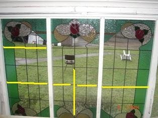
The two outer panels are supported appropriately. I believe the right one is adequately reinforced, and the left is over reinforced, but there will be no harm. The middle one is not adequately reinforced. The broken horizontal reinforcement transfers the stresses to the middle. The vertical one also transfers the stresses to the middle, only a little higher.
For reinforcement to work, it needs to transfer the stresses to the sides/tops of the panel where they will be captured by the framing. Thus the reinforcement needs to be a continuous line. The strongest reinforcement will be across the shortest dimension of the opening.
The weaving of the lead lines described by you as “lead lines do not go more than 2 pieces of glass before they are crossed by another piece of lead to break up that hinge thing” is exactly the right thing to do in these panels.
In the case you are illustrating, there should be no problems for several generations at minimum and possibly for a century.
"I’ve also included one other piece I’ve designed and cut which is going to be installed in an internal wall inside a home. Its 800/800mm approx and due to it being kept out of the weather was wondering about what type of re-enforcement structure would suit?"

As this will be an internal panel, I suggest that the best reinforcement would be a toughened/tempered sheet of 4mm float glass installed behind the panel. This will provide support in case someone leans against it. Yes, there is a diagonal hinge at the trunk, but the strongest reinforcing for this would simply be a horizontal bar behind the panel, which would look ugly and I don't think you want anyway.
“I was wondering if I would be able to ask you a question regarding re-enforcements. In regards to the hollow lead with the bar running through or using Reforce with the brass molded through it. Which is better?”
The lead covered steel is stronger. It has the disadvantage that if it gets moisture into it, it will corrode. Steel expands when it corrodes. This leads to progressive destruction of the surrounding glass.
Brass is weaker, but does not have the same degree of expansion when corroding.
Steel is cheaper than brass.
These factors have to be taken into account when deciding on which to use. So I don’t have a definitive response for your situation.
Really any time you need to reinforce a panel, it is because it is too large to reliably support itself. Often this is because it is too tall or too wide. Big windows have always been built in sections, with each stacked upon top of the lower ones. There are saddle bars or ferramenta added to the window opening to strengthen the window.
It is important to note that in compression glass is much stronger than steel. It is when the glass is in tension that it is weaker. So what the reinforcement is doing is resisting any lateral movement. It is not holding the glass up. The glass can do that very well on its own. The glass is subject to lateral movement from wind pressures mostly. But in some situations as in doors, it is subject to inertial movements - the door closes and sometimes slams. In other installations there is vibration – such as sidelights. The re-enforcement is to counteract or reduce this movement.
In general, if the panel needs reinforcement, it is too large as a single panel, and needs to be built in several panels. Some people hate to have the line of the panel joints, but the eye generally ignores those straight lines (unless they are out of true horizontal or vertical).
Some questions you need to ask yourself about reinforcement are:
Do you really need to reinforce?
Must it be within the panel?
Can you use external support?
Why would two hinges be better than one?
Remember the reason for not having a hinge is because the glass is the strongest element in a leaded or copper foiled window. Therefore a window with complicated lines will be a stronger window as the glass interlocks. If you look at many older windows you will see a number of hinges, and the windows are still there. I attach an image of a stair window that has been in place for just under 100 years. It has a multiplicity of hinges. I am not saying don't concern yourself about hinges, but keep a sense of proportion.
Nowadays, I keep all my reinforcements to the surface of the panels, not inside. Also if you want to join panels in a large window, it is not essential that the join be horizontal or vertical. It could be in a wave, sinuous curve or in a stepped fashion. Your imagination is probably the limit here, not the material.
The enquirer then sent pictures with further information.
“These are the latest 3 panels I’ve made for my bungalow out the back. They measure 1100mm high by 500 wide approx. I’ve made them all with different reinforcement applications. I was told they would not need any but still wanted to strength them up.
“The middle you can see I broke the hinge line with two pieces of re-force and on the other two I’ve gone all the way through to the outer border. All other lead lines do not go more than 2 pieces of glass before they are crossed by another piece of lead to break up that hinge thing.
“Due to the size/design I’d appreciate your thoughts on what I’ve done being correct/overkill?”
The two outer panels are supported appropriately. I believe the right one is adequately reinforced, and the left is over reinforced, but there will be no harm. The middle one is not adequately reinforced. The broken horizontal reinforcement transfers the stresses to the middle. The vertical one also transfers the stresses to the middle, only a little higher.
For reinforcement to work, it needs to transfer the stresses to the sides/tops of the panel where they will be captured by the framing. Thus the reinforcement needs to be a continuous line. The strongest reinforcement will be across the shortest dimension of the opening.
The weaving of the lead lines described by you as “lead lines do not go more than 2 pieces of glass before they are crossed by another piece of lead to break up that hinge thing” is exactly the right thing to do in these panels.
In the case you are illustrating, there should be no problems for several generations at minimum and possibly for a century.
"I’ve also included one other piece I’ve designed and cut which is going to be installed in an internal wall inside a home. Its 800/800mm approx and due to it being kept out of the weather was wondering about what type of re-enforcement structure would suit?"

As this will be an internal panel, I suggest that the best reinforcement would be a toughened/tempered sheet of 4mm float glass installed behind the panel. This will provide support in case someone leans against it. Yes, there is a diagonal hinge at the trunk, but the strongest reinforcing for this would simply be a horizontal bar behind the panel, which would look ugly and I don't think you want anyway.
Friday 17 July 2009
Positioning the Circle Cutter.
If you have a suction cup on the circle cutter, it will be easier to hold in place. But a three legged circle cutter is possible to keep in place too.
In both cases, one hand holds down the centre and the other operates the cutter. Make a test circle with no pressure to ensure before you start that the cutting bar will not bump into anything else on the bench. This also ensures that you have the circle to be cut placed appropriately on the glass.
To make the score start with the bar under your supporting arm and swing around to the other side of your arm until you hear the click or scratch indicating that you have come back to the start.
Monday 13 July 2009
Lead and Copper Foil in the Same Panel
It is possible to combine copper foil in a leaded glass panel.
The copper foiled piece should be soldered before inserting it into the lead came. In this way the soldered together pieces become very like another piece of glass.
There are some special considerations, of course.
The copper foiled piece should be designed as though it were a single piece of glass and so can be accommodated into the surrounding pieces of glass. Copper foiled piece should not have severe undercuts which would make it difficult to insert into the surrounding glass. It may be necessary to incorporate a piece of the surrounding colour to make it fit into the panel.
The copper foiled piece should be finished with all the beads on both sides. If one side is left flat, it will collect water if on the outside, and catch on any cleaning processes whichever side it is on. However, the piece should be tinned only on the outer edges. This will ensure that the copper foiled piece will slip into the came.
The image below illustrates a copper foiled piece incorporated into a leaded panel.

This section of the panel shows the accommodation of the main leaded panel with the copper foiled piece with a line from a petal to a leaf. Otherwise, it was fitted as one piece.
Wednesday 8 July 2009
Templates of openings, 6
When the opening is in stone, slight variations occur in the process of taking a template. The main difference is that the rebates are concealed. The rebates are slots into the stone. Thus, the template must slip into the slotted rebate. In these cases, the stiffer the material being used to take template, the better. Usually, thin plywood is the best material, as it has to be manipulated many times and in ways similar to the final panel.
Things are further complicated, as tracery is more common in stone than in timber framed openings. A complex opening shape may require two or more parts to enable the panel to be inserted. The taking of a template will help greatly in figuring out how the panel will be inserted into the opening.
Additionally, when the template is in position, you should mark the visible portion of the opening onto the template. Mark which is the inside and which the outside. Finally, mark on each template which side has the deeper slot as this will help in installation.
Monday 6 July 2009
Templates of Openings, 5 – Irregular Openings
Irregular openings such as trefoils and other tracery need to have templates taken with consideration on how the final panel can be put into the opening.
In the cases where the whole of the rebate is exposed, it is normally possible to put the panel in as a single whole piece.
So, the template is taken as for any other opening. It is more complex and time consuming as there are so many more sides than in a simple rectangular or circular opening.
In the cases where the whole of the rebate is exposed, it is normally possible to put the panel in as a single whole piece.
So, the template is taken as for any other opening. It is more complex and time consuming as there are so many more sides than in a simple rectangular or circular opening.
Subscribe to:
Posts (Atom)