Separators for kiln forming come in various
forms. Chemicals, liquids, sprays, refractory fibre paper, kiln wash, and others
I suppose. Which is best? Each separator
has its uses. No one is useful in all circumstances. Some will be
best for one circumstance and others for another.
Boron nitride
Boron nitride (BN) is
a high temperature lubricant. It can be sprayed or brushed onto the mould. It
adheres to smooth non-absorbent surfaces.
BN is among the most expensive of separators for glass. It seems most
useful on detailed, texture and casting moulds. BN is often recommended for
steel moulds as it adheres to it better than kiln wash. Although kiln
wash will work as a separator on steel, boron nitride is easier to apply.
Various conditions apply to its use.
Kiln wash
Kiln wash works
well on slightly absorbent surfaces – ceramic moulds, and shelves, for example.
It is the least expensive form of separator. It is shipped as a powder to which five parts water
is added to one of the powder. This
makes a liquid that can be applied to any appropriate surface. It can be sprayed or brushed. The mix can be
with less water on very absorbent surfaces, showing some of its
flexibility.
Almost all kiln
washes contain kaolin which helps keep the alumina hydrate in suspension. But most importantly, allows the solution to
be applied evenly.However, the same
kaolin also slowly changes to a crystalline substance by 900ºC/ 1650º that
sticks to glass. It needs to be re-applied after every full fuse.
Refractory fibre paper
Shelf paper works
well on flat surfaces and simple moulds. It is a moderately priced
separator.Two of the popular trade
names are Papyros and Thinfire.They
both contain alumina hydrate but with different binders.They provide a smooth surface for the shelf
and cylindrical shapes. They are not so good at separating glass from irregular
surfaces and incised details.The shelf
paper disintegrates after firing. Although it can sometimes be used several
times if undisturbed.The resulting
powder is an irritant and should be disposed of carefully.
There are thicker refractory
fibre papers.These normally range from 0.5mm
to 6mm.Thicker versions are called
blanket.These have the same characteristics
as shelf papers, although coarser.They
also do not use binders to keep them together.These are most useful in forming moulds and insulating glass from rapid
temperature changes.
The general
statement is that there is not one separator that is best in all circumstances.Each has its strengths.Knowledge of the objective of the firing and
its conditions will help in choosing the right one.
These notes are to
clarify some misconceptions about kiln wash use. Kiln wash is an economical glass separator that requires a little effort to use, but is effective and has less health risks than other separators. Kiln wash is a
separator, not a series of layers built up thickly. Some characteristics to
consider in its use.
Thickly applied kiln wash on a mould
The Mix
You mix
the powder with water.Use a thin mix - 1:5
by volume. There are various
descriptions of the thickness of the mix.Adhering to the 1:5 mix will ensure the right runniness of it.The mix must be frequently agitated to keep
the kiln wash in suspension while you are applying it.If you do not ensure all the kiln wash is in
suspension, you will not be applying enough separator.
Application
Use a soft bristled
brush such as a hake or broad squirrel brush to let kiln wash mix flow onto the
shelf or mould. Hold the brush almost
vertically and allow the kiln wash to flow off the brush while only lightly
touching the shelf with the bristles. Apply four thin layers in all directions – up/down,
horizontal, and the two diagonals - to ensure coverage.
Gentle application of kiln wash with a hake brush
Drying
No drying between
coats is advisable or necessary.The
addition of a wet coat over the dry will wet the previous layer(s) and will lead
to clumping.It is not like painting
wooden table that requires drying between coats. For kiln wash all the coats should be applied
without any drying between the directions of brushing.View this as applying one coat.And that is all that is needed.
Once the surface
has a dull look, it is ready to use, even though not thoroughly dry.At this stage, or later, you can remove any
brush marks.Place a sheet of paper over
the kiln wash. Smooth it by moving the
paper with the palm of your hand over the surface. Gently remove any dust.
Firing a newly kiln
washed shelf or mould with the glass on top will dry the kiln wash before glass
is soft enough to stick to it.
Removal
It is advisable to
remove the kiln wash once it has been fired to full fuse.The kaolin in the kiln wash becomes
increasingly crystalline as the temperature rises. It is fully crystalline at
about 900ºC/1650ºF. At the first full fuse it does not stick to transparent,
but often to some opalescent glass. On the second full fuse the kiln wash
sticks to all the glass.At tack fuse
temperatures, the kaolin has not fully crystallised, and several firings can be
achieved without difficulty.Experience
will show how many firings - at your tack fuse temperature – are possible.
Re-coating
Painting over used dry
kiln wash has the same difficulty of clumping as when initially applying.It is also easier to remove kiln wash that
has been fired only a few times. Kiln wash fired to full fuse several times requires
much more effort than one fired to full fuse once.
Safety
Kiln wash contains alumina hydrate and most commonly kaolin. The powdered forms of these are irritants, not health hazards. It is advisable to protect yourself and your work area. Wear a dust mask when removing the dry kiln wash. Do this is a well ventilated area or outside to reduce the dust in your studio. Dispose of the used kiln wash in sealed bags to avoid spreading the dust during refuse operations.
“I would like to use 1/4 inch Fiberfrax to impart texture on
the back of transparent glass. Is there a way to make it reusable?
I tried mould hardener on a small piece of it, but the hardener wasn’t
absorbed. I’m afraid the fiberfrax will lose its structure if I pre-fire
it (to burn out the binders) before removing it to apply hardener.”
It is difficult to
reuse refractory fibre paper after moving it between firings, but not
impossible. I have used two processes. One is to place the glass over the
cut fibre paper. This works for small pieces. The fibre paper was placed on
thinfire to allow air migration out. I used a long low temperature bubble
squeeze to ensure the binder was completely burned out.
The other arrangement
I have used for larger pieces.This is
to assemble and fire the fibre paper to burn out binders. There is a large chance that not enough air
will get to the centre of the fibre paper when large glass is placed on top.Binder not burned out leaves a brown mark on
the fibre paper and stains the glass grey. Turn off the kiln once all the
binder is burned out as evidenced by the paper returning to white.As soon as the temperature in the kiln is
comfortable, you can place glass on top of the fibre paper.It is strong enough that it will not be
compacted by the weight of the glass.
Using un-hardened fibre
But there is no
logical reason for these processes, although they work. Firing to about 500ºC/930ºF with a suitably
long soak will clear those gasses before the forming of the glass begins. You will know when there no longer is a smell of
burning paper, or on more recent fibres a chemical smell.Make sure you vent the kiln during this
burnout to allow the smoke to escape.For
a large area, a soak there may need to be hours long.Another check is when the fibre has turned
white again, the binders are gone.A further
protection against bubbles in any area is to place the whole assembly on a bed
of fibre paper.
It is possible to
use un-hardened refractory fibre without a separator, as the older versions do
not stick to glass easily.However, if
you are using the current eco fibres, they will stick in many areas.Kiln washing any fibre before firing is the best protection against lengthy clean ups. It also allows the best chance to remove the un-rigidised fibre for re-use.
A smoother surface
can be given to the refractory fibre, if you want. Do this by smoothing
powdered kiln wash over the bed layer and any other layers the glass will be
touching.An alternative to powdered kiln
wash is to put Thinfire or Papyros cut to shape over each layer.
After firing, slide
the fibre onto cardboard or another flat stiff surface. Then place into a
large pizza or similar box. I have stored fibre in such a way for several
firings.
Using hardened fibre
Of course, the
fibre can be hardened by use of colloidal silica.Make up the whole stack of fibre paper for
the kiln carving.Harden the whole stack
at once. This helps to bind the layers together.Brush on the hardener to the exposed part of each
layer. Cover both horizontal and
vertical surfaces. Hardener does take time to soak into the fibre paper.Give it time.You can add more hardener at intervals.Be careful to avoid overdoing it.Fully wet fibre is difficult to move and takes a long time to dry - days.The objective is to harden the surface of the
fibre, not to harden the whole by soaking it.
Allow the carrier
of the hardener to evaporate for hours or a day.When you can move the fibre, fire to at least
mid-700’s ºC/ 1300ºF to 1400ºF. After
firing, it must be covered with significant amounts of kiln wash. This can be
as a liquid or as powder. I prefer liquid. The kiln wash is required over all edges and
surfaces to keep the glass from sticking to the fibre.
Storage of the
rigidised fibre paper can be in the same way as for the fibre without binders
or hardener.
You can make your own billets from
small pot melts.But why should anyone
go to the effort? Some reasons are:
·You can make your own colour.
·You can use your cullet/scrap (avoiding buying
or making frit).
·You don’t have to buy and break billet to size
·You can reduce the clouding caused by many
microscopic bubbles surrounding the frit pieces.
·You can make a size to fit your casting
mould.
·Potentially, you will reduce needling.
Now
you are convinced of the advantages, you want to know how.
Preparation
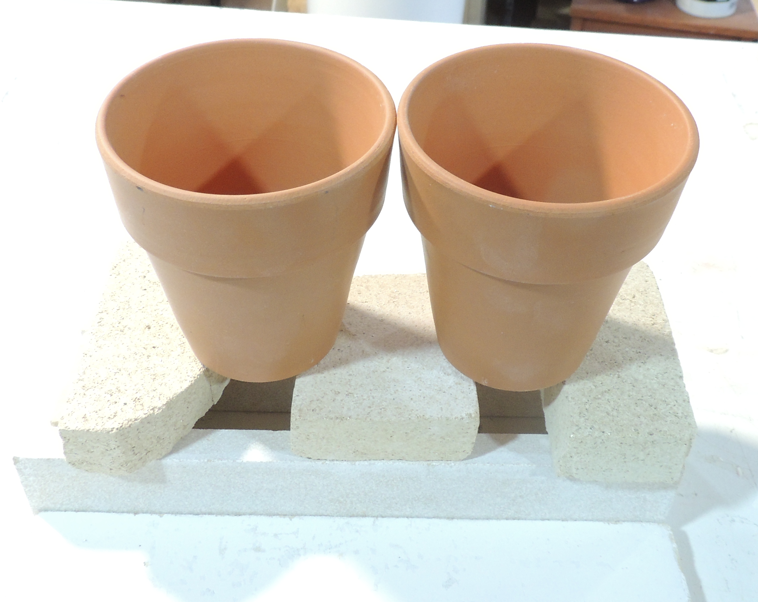
·Select the glass. Avoid iridised glass and any
ground edges – they will cause haze in the final casting. Wash all the glass. Place
the glass in a small flowerpot.
·Weigh out the amount of glass cullet needed for
the mould and add about 50gms to account for the glass that will stick to the
pot. Calculating the required weight is relatively simple and this post gives the information.
Dams
·Arrange dams in such a way that the resulting
billet will fit into the mould without overhang.It might be quite a tall billet. In which
case cast it horizontal with the height as the length of the billet.
·Line the dams with Thinfire/Papyros at least.
One mm fibre paper would be better.
·The dams can be on a kiln washed shelf or on
fibre paper. The bottom of the glass will be fine either way.
·Place the pot above the dams.The higher, the fewer bubbles in the
billet.And any left in the billet will
be reduced by flow in the casting firing.
·Multiple billets can be made of different
colours, sizes, etc., at the same time.
Firing
·Fire to around 900ºC/1650ºF and soak for hours.Observation will show when the pot is empty.Clue: There will be no string of glass from
the bottom of the pot.
·Anneal as for the smallest dimension.If you are doing multiple sizes, the dimension must be taken from the biggest piece.
·When cool, remove and clean the separator off the
pieces thoroughly.A 15 minute soak in a
5% citric acid solution will speed the process.
Casting
·Place billet in casting mould. The first ramp
rate needs to be for the smallest dimension of the billet.This may be a slower rate than when using frit for
casting.
·Do a long bubble squeeze in the 650ºC to 670ºC
range – up to two hours, but a minimum of one.
The statement that
a sheet of glass can be fused to itself is true in certain circumstances. It applies to transparent and some streaky
glasses best. These forms of glass are more
likely to fuse together successfully although not formulated for fusing.
Transparent and Streaky Glasses
Of course, the best practice is to test for compatibility. I found in my early days of sticking stained
glass together that it was beneficial to test. In doing so, I found Spectrum
and Armstrong transparent and streaky glass to be largely consistent across
many sheets. I did not have access to much
Kokomo or Wissmach. I cannot comment on
how their glass behaves in terms of compatibility across the production range. Not all transparent and streaky glass remains
stable at fusing temperatures. There are
some glasses that opalise, some change colour, some devitrify. This variability makes compatibility testing
important - even for the transparent form of stained glass.
Photo credit: Lead and Light
Wispy Glasses
The statement
about fusing to itself is less applicable to wispy glass. Not all the wispy stained glass from the same
sheet can be fused. It seems to be
dependent on the amount of opalescence in any one area of the glass. I found that it is possible - if you are very
careful - to fuse certain Spectrum wispies with the clear fusing standard on
top, but not on the bottom. This should
be applicable to other manufacturers’ wispy glass too.There must be a marginal compatibility that
is contained by the clear fusing glass on top, but I am not certain.
Photo credit: Lead and Light
Opalescent Glasses
The statement about
fusing to itself is almost completely inapplicable to opalescent glass. Stained glass opalescent glass does not have
the compatibility requirements of fusing glasses. They very often severely devitrify when taken
to fusing temperatures. This
devitrification means that opalescent stained glass is often not compatible
with itself. So, no amount of twiddling
with schedules will make stained glass opalescent glass fusible, even with
itself.
Manufacturers have
spent a lot of time and effort to produce fusing compatible opalescent glass. It is as though there is a minor element of
devitrification embodied in the opalising process. Whether this is so, it becomes very apparent on
doing compatibility testing that opalescent stained glass has severe devitrification
at fusing temperatures.
Stock photo
Compatibility Testing
It is important to
test for compatibility before committing to the main firing. Some transparent and streaky glass changes
colour, devitrifies, and some opalise at fusing temperatures. This applies with
even more force to wispies. They contain
a significant proportion of opalescence within them. Some opalescents are so unstable at fusing
temperatures that the devitrification becomes so bad the glass crumbles.
The importance of
testing pieces of the sheet for compatibility before committing to a firing is
reinforced by these factors.
Slumping
Slumping temperatures
are not so high as fusing, and it is often stated that single layers can be
slumped. Again, it is not always true.
Some glasses
change colour at slumping temperatures. A few opalise. It is not always certain what effect moderate
temperatures will have on stained glass. The compatibility testing will show. Observe the test firing at slumping
temperatures. Also, you will learn if
there are changes at moderate temperatures.
One element must
be commented upon about slumping. It is
important to have the edges finished to the appearance that you want the final
piece to have. The regularity of the
edges without bumps or divots, and the degree of polish need to be showing
before the firing starts. The slumping temperatures are not high enough to alter the shape or appearance of
the edges.
Firing of stained
glass to itself is normally a low risk activity, but with unpredictable results.
It can teach a lot about behaviour of
glass at higher temperatures. Slumping
single layer pieces can give information about the way single layers of glass
slump or drape. But testing is important
for fusing. And can inform about how the
glass will react at slumping temperatures too.
Most often
people are asked to listen to the sound of scoring.Unfortunately, different glass styles make
different sounds. Float glass makes a particular sound, transparent stained
glass makes a slightly different one, and opalescent glass makes almost no
sound. Consistent pressure of the right amount is important to the clean
breaking of glass. Therefore, we must learn to cut with the same consistent
pressure on all types of glass, rather than listening for sound.
It is easy
to tell when the scoring is too heavy. A
white line shows along the score.
The heavy score line near the break shows the white line and the irregular break
It is not
so easy to tell if the score is too light or just right.
A heavy score in the distance and a lighter score nearer
Pressure
The
general recommendations for the pressure to use during scoring is 4.5 – 7 Lbs
or 2 – 3 Kg. This is difficult to judge. I found that I needed a means of letting
people know for themselves the pressure they were exerting. It is not enough to
watch and say that was too hard, that was too soft, etc.
My method
of teaching novices how to judge the pressure they are using is to use a
digital kitchen scale that can have the scale set to zero. Place a piece of glass no larger than the platform on top of the scales.
Zero the scale display. Have someone watch the scale display while you
score in your usual way. Of course, you must not touch the glass with your
other hand. Have them tell you the maximum and minimum weights displayed. Keep
repeating until you can consistently use that 4.5 – 6.5 pounds (2 - 3Kg) pressure.
The testing setup showing a heavy score on the right and the start of a 1.9kg score on the left.
Consistency
The other
important element of scoring is to keep the pressure consistent throughout the
score. This test will also show how evenly you apply the pressure during the
score. The objective of scoring is to use the correct pressure throughout the
length of the score. If your pressure varies significantly during the score, it
will be difficult to get the glass to break consistently along the score line. Because
the amount of weakness in the surface created by the score is variable.
Your
observer can tell you when the pressure is less than optimum or more than
desired.If the pressure variation has a
reasonably consistent place in scoring - such as at the beginning, or on a
curve - you can fix it. Concentrate on correcting the fall off in pressure. For
example, most people start off with a lighter pressure than further into the
score.Getting the feel of the correct pressure
will enable you to apply it right from the start of the score. Sometimes,
people increase the scoring pressure when they come to curves. This test will
show if that is true for you.
This curve was scored with 4.3kg pressure showing that heavy pressure can result in break outs from the score line
This testing
can take quite a while. But it is worth the time spent in getting the scoring
pressure right to reduce the number of unwanted breaks. However, it is not a
one-time test. When I begin to have difficulties in breaking glass, I go back
to this test to check whether I am scoring too heavily. In my scoring practice,
I find that my best ones are those with 1.8 to 2.5kg (4.0 to 5.5 pounds) with
the cutter I use.This is less than
many, but it has worked well for me for years.
There are,
of course, other elements that go to making a good score and break. But the most
important thing in scoring and breaking opalescent glass is to avoid too heavy
a score by listening for a sound. Cut to a consistent pressure whatever sound
is heard.
I am amazed by the effort put into
ramp up rates, bubble squeezes, and top temperatures in comparison to
annealing. The emphasis on social media groups
seems to be to get the right ramp rates for tack fuses and slumps, bubble squeezes,
etc. Most of the attention is on the way
up to processing temperature.
The treatment of annealing and
cooling is almost cavalier by comparison. The attention seems to be on what temperature,
and how long a soak is needed. Then some
arbitrary rate is used to cool to 370ºC/700ºF.
Annealing, in comparison to firing to
top temperature, is both more complex and more vital to getting sound, lasting
projects completed.Skimping on
annealing is an unsound practice leading to a lot of post-firing difficulties.
Annealing is more than a temperature
and a time. It is also the cooling to
avoid inducing temporary stress. That stress during cooling can be large enough to break the glass. This temporary stress is due to expansion
differentials within the glass.
People often cite the saving of
electricity as the reason for turning off at 370ºC/700ºF. My response is that if the kiln is cooling off
slower than the rate set, there will be no electricity used. No electricity demands. No controller intervention. No relay operation.
Annealing at the lower end of the range
with a three-stage cooling provides good results.The results of Bullseye research on annealing
are shown in their chart for annealing thick items. It applies to glass 6mm and much larger. It results from a recommendation to anneal at
the lower end of the annealing range to get good anneals. Other industrial research shows annealing in
the lower end gives denser glass, and by implication, more robust glass. Wissmach have accepted the results of Bullseye
research and now recommend 482ºC/900ºF as the annealing temperature for their
W96. The annealing point of course
remains at 516ºC/960ºF.
Bullseye research goes on to show
that a progressive cooling gives the best results. They recommend a three-stage cooling process. The first is for the initial 55ºC/º100F below
the annealing temperature, a second 55ºC/100ºF cooling and a final cooling to
room temperature.
It is a good practice to schedule all
three cooling rates. It may be considered unnecessary because your kiln cools
slower than the chart indicates. Well,
that is fine until you get into tack and contour fusing. Then you will need the three-stage cooling
process as you will be annealing for thicknesses up to 2.5 times actual height.
Of course, you can find out all the
reasons for careful annealing in my book "Annealing; concepts, principles,
practice" Available from Bullseye at
A schedule was
presented for a slumping problem of a 6mm/0.25” blank. It consisted of three segments each of a rate
of 277C/500F with short holds up to 399C/750F and then a rapid rise to 745C/1375F.
The cool was done with two long holds at
537C/1000F and 482C/900F followed by cooling rates for 12mm/0.5”
My response was
that, yes it was fired too high. Not
only that, but the firing strategy, as shown by the schedule, is odd.
Strategy
The general
strategy for slumping follows these ideas.
·Glass
is slow to absorb heat, and in one sense, this schedule accepts that by having short
soaks at intervals.As glass is slow to
absorb heat, it is necessary to use slow ramp rates and without pauses and
changes in rates.This should be applied
all the way to the slumping temperature.
·Holds
of short durations are not effective at any stage in a slumping firing.The objective is to allow the glass time to
form to the mould with as little marking as possible.This implies slow rates to low temperatures
with significant holds at appropriate stages.This about putting enough heat work into the glass that higher
temperatures are not needed.
·This
kind of firing requires observation for new moulds and new arrangements of
glass to ensure the slump is complete.Once
you know the mould requirements and are repeating the layup of the glass, the
firing records will tell you what rates and times to use to get a complete
slump with minimum marking.
·The hold
at annealing temperature is to equalise the temperature throughout the glass to
produce a stress-free result.Any soaks
above are negated or repeated by the necessary soak at the annealing
temperature.The hold there must be long
enough to complete the temperature equalisation that is the annealing.
·My work
has shown that annealing for one (3mm/0.125”) layer thicker produces a piece
with less stress.This indicates that a
6mm/0.25” piece should be annealed as for 9mm/0.35” to get the best result.
The summary of the
firing strategy for slumping is:
·A
single ramp of a slow rate to the slumping temperature.
·Observation
of the progress of the slump to determine the lowest practical temperature and
hold time.
·Annealing
for one layer thicker that being slumped.
·Three
stage cooling of the piece at rates related to the annealing hold.
Critique
This is a critique of the schedule. For comparison, my schedule for a
full fused 6mm blank would be different.
·140ºC/250ºF
to 677º/1250ºF for 30 to 45 minutes.
·9999 to
482ºC/900ºF for 1.5 hours
·69ºC/124ºF
to 427ºC/800ºF, no hold
·125ºC/225ºF
to 371ºC/700ºF, no hold
·330ºC/600ºF
to room temperature, off.
The rate of the
published schedule is fast for a full fused blank and extremely fast for a tack
fused blank. This needs to be slowed. The
schedule provides a single (fast) rate of heating, but with unnecessary holds. The holds are so short as to be ineffective, anyway. There
is no need for the holds on the way up to the slumping temperature.In general slumping schedules are of fewer
segments. This is because glass behaves
well with steady slow inputs of heat.
Then strangely, the
schedule increases the rate to top temperature. It does so with a brief soak at 593ºC/1100ºF. This fast rate of 333ºC/ 600ºF begins at 400ºC/750ºF.This is still in the brittle phase of the
glass and risks breaking the glass.The
brittle stage ends around 540ºC/ 1005ºF.
This rapid rate
softens the surface and edges of the glass without allowing time for the
underside to catch up. This explains uneven
edges. It also risks breaking the glass
from too great expansion of the top before the bottom.
Additionally, the
schedule uses a temperature more than 55ºC/100ºF above what is a reasonable highest
slumping temperature.The top
temperature of this schedule is in the tack fusing range.
There is no need
for a hold 55ºC/100ºF above annealing soak. It is the annealing soak that
equalises the temperature before the cool begins.The higher temperature equalisation is
negated by the cooler soak at annealing temperature. So, the hold at the higher
temperature and slow cool to the annealing temperature only delays the firing
by about two hours.It does not have any
effect on the final piece.
The schedule is cooling for a piece of 12mm/0.5”.This is slower than necessary.As noted above, cooling for one layer thicker
than the piece is advisable to get the most stress free result. The annealing soak could be 1.5 hours
following this idea. Cooling with a
three stage schedule reduces the risk of inducing temporary stresses that might
break the glass. Although the initial
cooling rate I recommend is very similar to this schedule, it safely reduces the
total cooling time.
·69ºC/124ºF
to 427ºC/800ºF, no hold
·125ºC/225ºF
to 371ºC/700ºF, no hold
·330ºC/600ºF
to room temperature, off.
Using my kind of
schedule for the first time will require peeking once top temperature is
reached to determine when the slump is complete. It may take as much as an
hour. Be prepared to either extend the hold, or to skip to the next segment if
complete earlier. The controller manual will explain how.
More information is given in Low Temperature Kilnforming, An Evidence-based guide to scheduling. Available from Etsy and Bullseye
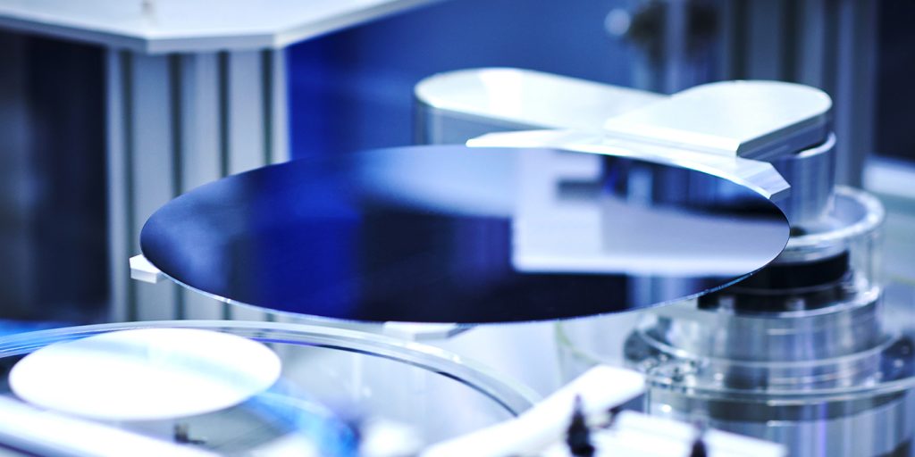
Robotic arm holding a silicon wafer for semiconductor processing. Image source: iStock.
A blog post by Krista Grayson of Mo-Sci rayson
In the fast-paced world of semiconductor manufacturing, where precision and reliability are paramount, choosing a suitable passivation material is critical to ensuring the optimal performance of electronic devices. Among the library of viable materials, glass has gained significant attention for its unique properties and versatility. This article looks at how glass is used for passivation and what properties make it highly suitable for the job.
Understanding Passivation in Semiconductors
Before unpacking the specifics of glass as a material for passivation, it is essential to understand the concept of passivation in semiconductor manufacturing. Passivation involves depositing a protective material onto the surface of metals or metal alloys to enhance their resistance to environmental factors.
The layering material can be organic or inorganic and should exhibit excellent electrical insulation and strong substrate adhesion, as well as block the ingress of chemical species. In the case of semiconductors, passivation is crucial to preventing degradation and ensuring long-term reliability.1,2
Why Use Glass for Passivation?
Glass has emerged as a compelling choice for passivation due to its unique combination of properties. For example, glass can be formulated in numerous ways, with common types including Pb-Si-Al, Zn-B-Si, and Pb-Zn-B. This allows manufacturers to produce glass capable of meeting low and high-voltage electrical specifications; matching the coefficient of thermal expansion of semiconductor materials; and meeting the low temperature processing requirements.3,4
Glass is chemically durable and thus can provide an inert barrier against external elements, such as moisture and contaminants, which might otherwise compromise the semiconductor’s performance. Moreover, the high transparency of some glasses, such as borosilicate glass, makes them ideal for applications with critical optical properties, such as photovoltaics. This transparency enables efficient energy transmission and absorption, contributing to the overall performance of semiconductor devices and solar cells.5,6
How are Semiconductors Passivated?
Glass can be deposited onto semiconductors in a variety of ways. Choosing methods for passivation depends on factors such as the semiconductor device’s specific requirements, the passivation layer’s desired properties, and the overall manufacturing process. Methods for achieving glass passivation in semiconductor manufacturing include:7
Chemical vapor deposition (CVD), including plasma-enhanced CVD (PECVD)
Physical vapor deposition (PVD), including E-beam deposition
Sputter Coating
Atomic Layer Deposition (ALD)
In manufacturing, the process of glass passivation is frequently succeeded by chemical procedures, such as the etching of contact windows or the electrolytic deposition of contacts. These procedures may pose a threat to the integrity of the glass.
The chemical resistance of different passivation glasses varies significantly and serves as a crucial factor in determining the suitable glass type and the accompanying etching process.8
Comparing Glass to Other Materials
While various materials can be used for passivation, glass stands out for its exceptional stability over temperature, humidity, and time. Literature searches reveal a lack of head-to-head comparisons with other common passivation materials; however, general comparisons can be drawn.6
Amorphous silicon (a-Si) films utilized in solar cells present numerous advantages. These include a lower deposition temperature, in contrast to the temperatures commonly employed in cell manufacturing. However, it is essential to note that a-Si films exhibit sensitivity to subsequent high-temperature processes, which are frequently necessary in industrial manufacturing technology.9
Similarly, AlOx passivation films can be applied at relatively low temperatures but can be limited by slow deposition speeds when using specific application methods. This can generate problems for high-throughput techniques, such as solar cell production.9
Polyimide, a common passivation material lauded for its strength and thermal stability, is also susceptible to moisture absorption. This can impact the strength and dielectric properties of the protective coating, risking the integrity of the semiconductor.10
Applications of Glass Passivation
Passivation glasses demonstrate outstanding performance in wafer passivation and encapsulation processes, providing advantages to a diverse range of semiconductor devices, including:8
Thyristors
Power transistors
Diodes
Rectifiers
Varistors
Glass also has applications in solar cell passivation. In a recent study, researchers developed a method for enhancing borosilicate glass (BSG) passivation using high temperatures before lowering the temperature to accommodate the metallization process. In doing so, they notably improved the solar cell’s efficiency.11
In another study, phosphosilicate glass (PSG) was found to significantly enhance the practical lifetime of minority carriers and improve the overall performance of solar cells, particularly in structures involving nanocrystalline silicon and crystalline silicon.12
Mo-Sci’s Expertise in Glass Thin Films
Fueled by the increasing prevalence of smart devices and advancements in the automotive and aerospace sectors, the semiconductor passivation glass market is anticipated to grow consistently in the next few years.3
Mo-Sci’s expertise lies in leveraging the unique properties of glass to create tailored solutions, ensuring the reliability and performance of many applications, including glass seals and glass coatings. Contact us for more information.
References and Further Reading
Pehkonen, S.O., et al. (2018). Chapter 2 – Self-Assembly Ultrathin Film Coatings for the Mitigation of Corrosion: General Considerations. Interface Science and Technology. doi.org/10.1016/B978-0-12-813584-6.00002-8
Lu, Q., et al. (2018). Chapter 5 – Polyimides for Electronic Applications. Advanced Polyimide Materials. doi.org/10.1016/B978-0-12-812640-0.00005-6
Zhong, C., et al. (2022). Properties and mechanism of amorphous lead aluminosilicate passivation layers used in semiconductor devices through molecular dynamic simulation. Ceramics International. doi.org/10.1016/j.ceramint.2022.07.191
Hansen, U., et al. (2009). Robust and Hermetic Borosilicate Glass Coatings by E-Beam Evaporation. Procedia Chemistry. doi.org/10.1016/j.proche.2009.07.019
Korvus Technology. [Online] The Revolution of PVD Systems in Thin Film Semiconductor Production. Available at: https://korvustech.com/thin-film-semiconductor/ (Accessed on 05 January 2024).
Liao, B., et al. (2021). Unlocking the potential of boronsilicate glass passivation for industrial tunnel oxide passivated contact solar cells. Progress in Photovoltaics. doi.org/10.1002/pip.3519
Imamura, K., et al. (2018). Effective passivation for nanocrystalline Si layer/crystalline Si solar cells by use of phosphosilicate glass. Solar Energy. doi.org/10.1016/j.solener.2018.04.063