There are several possible reasons for this.
The main one is that the soldering is too slow. This causes the adhesive on the foil to fail before the solder has a chance to become rigid.
The foil may not have stuck to the glass firmly. Reasons for this are many, but some are:
- Dirty glass. Make sure the glass is washed and polished clean, especially if you have been grinding, when you need to get all the glass dust out of the pits on the edges.
- Oils from your hands. The oils can be natural or from hand creams. If you have oily skin or need to use hand creams consider cotton gloves for use when handling the glass prior to and during foiling.
- Inadequate contact between the foil and the glass. This can be from both the above, but can also be that the foil was not pressed firmly to all the sides and edges of the glass pieces.
The foil adhesive may be inadequate through manufacture or age. If a test piece does not feel tacky to your finger tips, it is not going to stick to the glass very well.
Friday, 28 August 2009
Monday, 24 August 2009
Grinding for Copper Foil
It is often thought that every piece of glass has to be ground to enable the foil to stick well to it. There are conflicting views about this. I am firmly on the side of not grinding. The impact adhesive on the back of the foil is thin and will not fill the depressions caused by grinding. It will adhere to a smooth surface more strongly than a rough one. Remember the purpose of the foil is to provide a surface to carry the solder. It keeps the foil in place until the solder bead is completed on both sides. It is not a permanent adhesive. So some of the discussion about which surface is best is academic.
There are ways of obtaining clean cuts that help avoid the need to grind.
Score with an even pressure. This helps the glass break clean with few shells or chips. If there are any overhangs, you can eliminate them with a quick wipe of the edge of the cut piece on the waste piece.
Ensure you hold your cutter vertically. This will encourage the break to be at right angles to the surface giving a clean smooth cut face.
The only NEED for grinding is to adjust an inaccurate cut. We all make inaccurate cuts from time to time.
Friday, 21 August 2009
Copper Foil Oxidisation
Protection of foiled pieces from oxidisation
If foiled pieces are going to sit a while before soldering, put them in a sealed plastic bag with the air squeezed out. This will prolong the time before the oxidization becomes a problem for the soldering process.
Another possibility is to tin all the pieces before putting them away in the plastic bag. Solder oxidizes more slowly than copper does.
Thursday, 13 August 2009
Transparency Sketches
Use matt finish acetate .25 to .12mm thick. This will later be fixed to Perspex for presentation.
You will need rigger brushes in sizes 0, 1, 2, and 4 for doing the lead lines and other areas of graphic delineation. In using these brushes for lead lines, you want to maintain a line that is consistently thick. It is a different feeling from general image making and you may want to try locking your wrist to maintain a greater consistency of pressure.The paint for the lead lines can be a calligraphy ink or a black acrylic paint. The lead lines and all other tracing is applied to the matt side of the acetate.
Once the tracing lines are all completed, start laying the colours on the backside, the smooth side. The brushes to use are bulbous pointed sables in sizes 2, 3, 5 and 6. The application is in a "floated" versus a "stroked" manner of application. Stroking has a tendency to hasten the drying resulting in streaking. You may find this a bit of a trick at first. It is advisable to place colour throughout the design so it has time to set up and dry a bit, as opposed to putting wet against wet.
When the colour has dried, one can emulate matting on the matt side with an ebony pencil. And if you want to take out some lights, that can be accomplished with carefully placed extender. The extender is also used to make the piece transparent and to emulate a variety of textures available in glass from reamy to seedy.
When the colours are dry, mount the sketch on 3mm Perspex to stiffen the presentation, provide weight and give the presentation with some "substance”. You can also add double matt board doors hinged with smooth electrical tape to keep the lacquer colours away from sustained sun. Also when open, they support the sketch during the presentation.
When putting matting boards around the presentation sketch, they should be much wider than a drawing or water colour so that ambient light from behind is modified by a greater expanse of black or dark matting board.
Edited from emails by Richard Millard
Tuesday, 11 August 2009
Oxidized Copper Foiled Pieces
If copper foiled pieces sit out for any length of time after foiling they will oxidize. This means that the solder will not stick to the foil, as it requires a clean surface to attach to.
Clean the foiled pieces with fine steel wool, pot scrubber or flexible mild abrasive. Make sure you do not damage the foil or pull it up from the glass during this process. It is likely that the adhesive holding the foil to the glass is not as strong as it once was.
I do not recommend using a stronger flux to overcome the oxidisation, as this is often highly acidic and may damage the glass.
Once cleaned, you can flux the foil and proceed as normal.
Friday, 31 July 2009
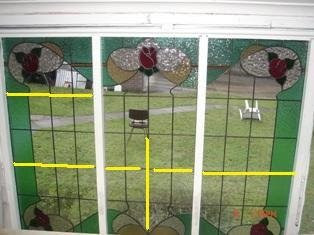
Weaving in Leaded Glass
"Weaving" is only easily and fully done where there is a grid. The example below shows a restoration project where the main part of the panel is a grid.
This image shows the starting of the weaving. A short lead covering only one quarry has been placed horizontally - although you can start with a short vertical, both are fine. The next lead is vertical and covers two of the quarries. As you can see here the two quarries at the right are ready for the longer horizontal to be placed.

You proceed in this fashion - alternating long and short leads throughout the grid area.
As you can see this builds up in a diagonal fashion with each vertical and horizontal line being interrupted after every second piece of glass.
If you look closely you can also see that these leads are being tucked. This is easier with leads of 7mm and greater than of 6mm and less.
This method of leading gets its name from the similarity to representations of weaving in illustrations where a broken line represents the thread or reed going under another. Its purpose is to avoid hinges and so strengthen the whole panel. This avoidance of hinges makes the turning of the panel during soldering and cementing much easier.
Of course, you must remember that the glass is the strongest part of the panel.
Monday, 27 July 2009
Direct or Trace cutting
Place the glass over the pattern and run the cutter along the pattern lines you see by looking through the glass. There's no need to draw lines on the glass. For translucent glass you may need a light box.
You should be aiming to cut glass efficiently and accurately. Trace cutting is the most efficient, as it completes in a single operation what other methods –such as drawing on the glass or making templates from the cartoon - take several steps to accomplish.
It is more accurate because each extra step required for other methods increases the possibility for error. The fewer times you copy the original pattern lines, the less likely you are to diverge from the original pattern lines.
It is very important to keep the cutter at right angles to the glass - as seen from side to side, not vertical. This of course is true of all cutting. It makes the cutting inaccurate, because the light is bent when coming through the glass much like water changes the apparent angle of sight into its depths. Tilted cutters also have undesirable effects when breaking the glass.
Friday, 24 July 2009
Tinning brass vase caps
Tinning brass vase caps can help in obtaining a secure joint without long dwells at each joint that risk overheating the glass.
Heat your vase cap with a torch of one kind or another. You can heat until it becomes a dull red. The quickly brush or rub (with a cloth) flux onto the inside and outside of the rim of the vase cap. Apply a little solder to the fluxed area while everything is still hot. This will tin all the areas where the flux was placed.
This method will give a strong solder to solder joint that requires much less time when soldering the cap to the rest of the lamp shade.
Wednesday, 22 July 2009
Leaded Glass Reinforcements
I received a query recently about this subject. As the correspondence may be useful to a more general audience, I present an edited version here. (all the personal chat has been taken out!)
“I was wondering if I would be able to ask you a question regarding re-enforcements. In regards to the hollow lead with the bar running through or using Reforce with the brass molded through it. Which is better?”
The lead covered steel is stronger. It has the disadvantage that if it gets moisture into it, it will corrode. Steel expands when it corrodes. This leads to progressive destruction of the surrounding glass.
Brass is weaker, but does not have the same degree of expansion when corroding.
Steel is cheaper than brass.
These factors have to be taken into account when deciding on which to use. So I don’t have a definitive response for your situation.
Really any time you need to reinforce a panel, it is because it is too large to reliably support itself. Often this is because it is too tall or too wide. Big windows have always been built in sections, with each stacked upon top of the lower ones. There are saddle bars or ferramenta added to the window opening to strengthen the window.
It is important to note that in compression glass is much stronger than steel. It is when the glass is in tension that it is weaker. So what the reinforcement is doing is resisting any lateral movement. It is not holding the glass up. The glass can do that very well on its own. The glass is subject to lateral movement from wind pressures mostly. But in some situations as in doors, it is subject to inertial movements - the door closes and sometimes slams. In other installations there is vibration – such as sidelights. The re-enforcement is to counteract or reduce this movement.
In general, if the panel needs reinforcement, it is too large as a single panel, and needs to be built in several panels. Some people hate to have the line of the panel joints, but the eye generally ignores those straight lines (unless they are out of true horizontal or vertical).
Some questions you need to ask yourself about reinforcement are:
Do you really need to reinforce?
Must it be within the panel?
Can you use external support?
Why would two hinges be better than one?
Remember the reason for not having a hinge is because the glass is the strongest element in a leaded or copper foiled window. Therefore a window with complicated lines will be a stronger window as the glass interlocks. If you look at many older windows you will see a number of hinges, and the windows are still there. I attach an image of a stair window that has been in place for just under 100 years. It has a multiplicity of hinges. I am not saying don't concern yourself about hinges, but keep a sense of proportion.

Nowadays, I keep all my reinforcements to the surface of the panels, not inside. Also if you want to join panels in a large window, it is not essential that the join be horizontal or vertical. It could be in a wave, sinuous curve or in a stepped fashion. Your imagination is probably the limit here, not the material.
The enquirer then sent pictures with further information.
“These are the latest 3 panels I’ve made for my bungalow out the back. They measure 1100mm high by 500 wide approx. I’ve made them all with different reinforcement applications. I was told they would not need any but still wanted to strength them up.
“The middle you can see I broke the hinge line with two pieces of re-force and on the other two I’ve gone all the way through to the outer border. All other lead lines do not go more than 2 pieces of glass before they are crossed by another piece of lead to break up that hinge thing.
“Due to the size/design I’d appreciate your thoughts on what I’ve done being correct/overkill?”
The two outer panels are supported appropriately. I believe the right one is adequately reinforced, and the left is over reinforced, but there will be no harm. The middle one is not adequately reinforced. The broken horizontal reinforcement transfers the stresses to the middle. The vertical one also transfers the stresses to the middle, only a little higher.
For reinforcement to work, it needs to transfer the stresses to the sides/tops of the panel where they will be captured by the framing. Thus the reinforcement needs to be a continuous line. The strongest reinforcement will be across the shortest dimension of the opening.
The weaving of the lead lines described by you as “lead lines do not go more than 2 pieces of glass before they are crossed by another piece of lead to break up that hinge thing” is exactly the right thing to do in these panels.
In the case you are illustrating, there should be no problems for several generations at minimum and possibly for a century.
"I’ve also included one other piece I’ve designed and cut which is going to be installed in an internal wall inside a home. Its 800/800mm approx and due to it being kept out of the weather was wondering about what type of re-enforcement structure would suit?"

As this will be an internal panel, I suggest that the best reinforcement would be a toughened/tempered sheet of 4mm float glass installed behind the panel. This will provide support in case someone leans against it. Yes, there is a diagonal hinge at the trunk, but the strongest reinforcing for this would simply be a horizontal bar behind the panel, which would look ugly and I don't think you want anyway.
“I was wondering if I would be able to ask you a question regarding re-enforcements. In regards to the hollow lead with the bar running through or using Reforce with the brass molded through it. Which is better?”
The lead covered steel is stronger. It has the disadvantage that if it gets moisture into it, it will corrode. Steel expands when it corrodes. This leads to progressive destruction of the surrounding glass.
Brass is weaker, but does not have the same degree of expansion when corroding.
Steel is cheaper than brass.
These factors have to be taken into account when deciding on which to use. So I don’t have a definitive response for your situation.
Really any time you need to reinforce a panel, it is because it is too large to reliably support itself. Often this is because it is too tall or too wide. Big windows have always been built in sections, with each stacked upon top of the lower ones. There are saddle bars or ferramenta added to the window opening to strengthen the window.
It is important to note that in compression glass is much stronger than steel. It is when the glass is in tension that it is weaker. So what the reinforcement is doing is resisting any lateral movement. It is not holding the glass up. The glass can do that very well on its own. The glass is subject to lateral movement from wind pressures mostly. But in some situations as in doors, it is subject to inertial movements - the door closes and sometimes slams. In other installations there is vibration – such as sidelights. The re-enforcement is to counteract or reduce this movement.
In general, if the panel needs reinforcement, it is too large as a single panel, and needs to be built in several panels. Some people hate to have the line of the panel joints, but the eye generally ignores those straight lines (unless they are out of true horizontal or vertical).
Some questions you need to ask yourself about reinforcement are:
Do you really need to reinforce?
Must it be within the panel?
Can you use external support?
Why would two hinges be better than one?
Remember the reason for not having a hinge is because the glass is the strongest element in a leaded or copper foiled window. Therefore a window with complicated lines will be a stronger window as the glass interlocks. If you look at many older windows you will see a number of hinges, and the windows are still there. I attach an image of a stair window that has been in place for just under 100 years. It has a multiplicity of hinges. I am not saying don't concern yourself about hinges, but keep a sense of proportion.
Nowadays, I keep all my reinforcements to the surface of the panels, not inside. Also if you want to join panels in a large window, it is not essential that the join be horizontal or vertical. It could be in a wave, sinuous curve or in a stepped fashion. Your imagination is probably the limit here, not the material.
The enquirer then sent pictures with further information.
“These are the latest 3 panels I’ve made for my bungalow out the back. They measure 1100mm high by 500 wide approx. I’ve made them all with different reinforcement applications. I was told they would not need any but still wanted to strength them up.
“The middle you can see I broke the hinge line with two pieces of re-force and on the other two I’ve gone all the way through to the outer border. All other lead lines do not go more than 2 pieces of glass before they are crossed by another piece of lead to break up that hinge thing.
“Due to the size/design I’d appreciate your thoughts on what I’ve done being correct/overkill?”
The two outer panels are supported appropriately. I believe the right one is adequately reinforced, and the left is over reinforced, but there will be no harm. The middle one is not adequately reinforced. The broken horizontal reinforcement transfers the stresses to the middle. The vertical one also transfers the stresses to the middle, only a little higher.
For reinforcement to work, it needs to transfer the stresses to the sides/tops of the panel where they will be captured by the framing. Thus the reinforcement needs to be a continuous line. The strongest reinforcement will be across the shortest dimension of the opening.
The weaving of the lead lines described by you as “lead lines do not go more than 2 pieces of glass before they are crossed by another piece of lead to break up that hinge thing” is exactly the right thing to do in these panels.
In the case you are illustrating, there should be no problems for several generations at minimum and possibly for a century.
"I’ve also included one other piece I’ve designed and cut which is going to be installed in an internal wall inside a home. Its 800/800mm approx and due to it being kept out of the weather was wondering about what type of re-enforcement structure would suit?"

As this will be an internal panel, I suggest that the best reinforcement would be a toughened/tempered sheet of 4mm float glass installed behind the panel. This will provide support in case someone leans against it. Yes, there is a diagonal hinge at the trunk, but the strongest reinforcing for this would simply be a horizontal bar behind the panel, which would look ugly and I don't think you want anyway.
Friday, 17 July 2009
Positioning the Circle Cutter.
If you have a suction cup on the circle cutter, it will be easier to hold in place. But a three legged circle cutter is possible to keep in place too.
In both cases, one hand holds down the centre and the other operates the cutter. Make a test circle with no pressure to ensure before you start that the cutting bar will not bump into anything else on the bench. This also ensures that you have the circle to be cut placed appropriately on the glass.
To make the score start with the bar under your supporting arm and swing around to the other side of your arm until you hear the click or scratch indicating that you have come back to the start.
Monday, 13 July 2009
Lead and Copper Foil in the Same Panel
It is possible to combine copper foil in a leaded glass panel.
The copper foiled piece should be soldered before inserting it into the lead came. In this way the soldered together pieces become very like another piece of glass.
There are some special considerations, of course.
The copper foiled piece should be designed as though it were a single piece of glass and so can be accommodated into the surrounding pieces of glass. Copper foiled piece should not have severe undercuts which would make it difficult to insert into the surrounding glass. It may be necessary to incorporate a piece of the surrounding colour to make it fit into the panel.
The copper foiled piece should be finished with all the beads on both sides. If one side is left flat, it will collect water if on the outside, and catch on any cleaning processes whichever side it is on. However, the piece should be tinned only on the outer edges. This will ensure that the copper foiled piece will slip into the came.
The image below illustrates a copper foiled piece incorporated into a leaded panel.

This section of the panel shows the accommodation of the main leaded panel with the copper foiled piece with a line from a petal to a leaf. Otherwise, it was fitted as one piece.
Wednesday, 8 July 2009
Templates of openings, 6
When the opening is in stone, slight variations occur in the process of taking a template. The main difference is that the rebates are concealed. The rebates are slots into the stone. Thus, the template must slip into the slotted rebate. In these cases, the stiffer the material being used to take template, the better. Usually, thin plywood is the best material, as it has to be manipulated many times and in ways similar to the final panel.
Things are further complicated, as tracery is more common in stone than in timber framed openings. A complex opening shape may require two or more parts to enable the panel to be inserted. The taking of a template will help greatly in figuring out how the panel will be inserted into the opening.
Additionally, when the template is in position, you should mark the visible portion of the opening onto the template. Mark which is the inside and which the outside. Finally, mark on each template which side has the deeper slot as this will help in installation.
Monday, 6 July 2009
Templates of Openings, 5 – Irregular Openings
Irregular openings such as trefoils and other tracery need to have templates taken with consideration on how the final panel can be put into the opening.
In the cases where the whole of the rebate is exposed, it is normally possible to put the panel in as a single whole piece.
So, the template is taken as for any other opening. It is more complex and time consuming as there are so many more sides than in a simple rectangular or circular opening.
In the cases where the whole of the rebate is exposed, it is normally possible to put the panel in as a single whole piece.
So, the template is taken as for any other opening. It is more complex and time consuming as there are so many more sides than in a simple rectangular or circular opening.
Saturday, 4 July 2009
Templates of openings, 4
Round headed openings can be considered as a special case of a circle.
The horizontal you must find is the shoulder of the window. This is the place from which the curve springs on each side. The opening is generally vertical up to this point and then begins the curve.
You need to make sure you have marked where this shoulder is on the template. You should indicate any reference points from the frame onto the template.
The join to the lower part of the window must be made obvious. Normally there will be an overlap between the lower rectangular template and this approximate half circle. You need to mark where this overlap occurs, if you do not fasten the two sheets together. This can be done by marking across the two sheets in a few places. This will enable you to join them exactly back at the studio.
Thursday, 2 July 2009
Templates of openings, 3 - Circles
Occasionally the window is circular and sometimes an oval. In both cases a template is important. The circle rarely is exact. Take the template in the normal way and then ensure you mark the verticals and horizontals for the opening. You often can use the jointing in the woodwork to help with these. Also mark any other reference points from the opening. Finally, mark which is the outside and which the inside.
This procedure will ensure that you will be able to fit the panel into the opening.
This procedure will ensure that you will be able to fit the panel into the opening.
Tuesday, 30 June 2009
Templates of Openings, 2
Irregular rectangles
If you have found or can see that the opening is not a true rectangle and cannot determine where any right angles are, you need to take a template.
The objective is to make a piece that will fit into the opening without bending or being too small for the space. It will be the same size as the finished panel and so you will be able to put the finished panel into the opening without needing to trim or expand the panel.
First, trim the sheet of material you have chosen to use to a size a little larger than the measured size. Place the uncut side along one of the long sides of the opening. If the opening is a portrait format, place it on the right or left side as convenient to you.
Next, adjust the bottom by marking a line on the sheet. This is where a second person is very useful. One person can hold the sheet in place on outside of the opening and the other do the marking from the inside –in the case of the rebate being on the outside and vice versa if the rebate is on the inside. The marked line should be as close to the edge of the rebate as possible. The special case of an opening in stone will be dealt with separately.
Then take the sheet to a place where it can be safely cut. A long metal straight edge and craft or “Stanley” knife are often the best aids to cutting straight lines. Replace the sheet into the opening after cutting, and make any adjustments to the size and angles of the sheet at the bottom by marking and cutting as necessary.
When the side and bottom are adjusted, start on the other side. Proceed as for the bottom.
When the side is finished, start on the top.
Finally, present the whole sheet to the opening to make sure it slips into place with no snags, or bending of the sheet.
It may be that the opening is too large for a single sheet. In that case you will need to work with two or more sheets and try them together for the final fitting into the opening. You can put them together in the window. You can fasten them together with tape or other fasteners to make one sheet. You can also make two parallel lines both at angles and at intervals across the sheet so that when you get back to the studio you can exactly reproduce the full sheet by matching the marks and then firmly fastening them together. This makes transport of large templates much easier.
You will know that a panel made to a template made in this way will fit into the opening, no matter how irregular the opening may be.
Friday, 26 June 2009
Templates of Openings, 1
If you have an irregular opening, it may be best to take a tracing of the opening. Usually this will be in a larger opening and so a helper may be necessary to hold things.
The material used to take the template must have a few characteristics:
- It must be stiff enough to have the minimum possible bend over the width or height of the opening
- It must be easy to mark with a pencil or other implement
- It must be easy to cut or shape
- It should be light to make it easy to lift it to the opening for the many adjustments that will be required.
A number of materials can be used: stiff card, mounting board, corrugated cardboard, thin plywood, and many other sheet materials. I have found stiff corrugated cardboard easy to use.
More information in this series is at:
Irregular rectangles
Circles
Round headed windows
Irregular shapes
Stone
Monday, 22 June 2009
Measuring a Rectangular Opening.
1 - Measure at both the top and bottom for width.
2 - Measure at the left and right sides for height.
If it is a tall or wide opening measure at intervals and at least in the middle of each side.
So far so good. But how do you know that it is a rectangle rather than a parallelogram? Measure the diagonals – bottom left to top right and top left to bottom right. If these measurements are equal or +/- 5mm you can consider the opening to be a rectangle.
With bigger variations you may set out the cartoon using the measurements for the opening. Still, you need to know where the right angles are, if there are any, to be able to set out the cartoon to properly fit the opening.
So you may wish to take a template of the opening.
Saturday, 13 June 2009
Bulging lead panels
There is probably no means by which leaded glass, because of the innate character of lead as its skeleton, can resist its propensity to bend, bulge and sag. Evidence of these occurrences does not necessarily foretell disaster or immediate collapse. Bulging does not necessarily indicate the need for action or re-leading.
There are three basic stages through which stained glass passes on the way to requiring repair;
1. Bulging, bending and sagging
2. Loss of putty and breaking of solder joints
3. Unhousing of the glass from the lead
The points at which solder joints break depends on the materials used.
Since lead, compared with solder, is a resilient material abutting the more resistant solder, breaks will occur most frequently at the junction of the solder with the lead.
With zinc, the situation is reversed. The zinc is of greater resistance than the solder. As a result the break most often occurs on the solder at the point of the zinc junctions.
It is the very existence of resilience in lead which responds to the expansion and contraction of glass that permits the more healthy survival of the glass over the less sympathetic accommodations of either zinc or copper foil. Leaded glass, unlike any other medium, has the unique capability of having its skeleton (lead) replaced, when the need arises, without damaging its body (glass).
Wednesday, 10 June 2009
Combing Glass
This process is done at relatively high temperatures for fusers – around 925C. It consists of pulling or dragging the surface of the hot glass to produce a marbling effect.
Preparation:
A batt washed ceramic shelf is the best surface. You can use fibre paper on your shelf, but you must be careful to avoid raking deeply enough so that you pick up the fibre and drag it into the glass.
Make a boundary with 10-12mm fibre board on your shelf. You can use strips - for the most efficient use of the board – or cut a shape from a sheet. If you are using strips, fasten them together with wire staples. This will resist the glass flowing at the edges.

Place the glass into the space created by the fibre board. You can place 10mm strips on edge to form very tight lines, you can shingle glass to give broader lines, or you can place the glass in a more random way to give quite different effects.

When shingling or placing glass randomly, it is often best to cut a sheet of iridised clear to lie on the bottom to ensure you have enough depth of glass. Placing the iridised side of glass down toward the shelf provides an additional release, and can give added interest to the back. Anything less than 8-10mm thick leaves the glass pulled away from the edges in the direction of the combing.
Firing:
The initial temperature rise can be fast because the glass is made up of narrow strips. No bubble squeeze is required for the vertical or shingled strips, as there are easy ways for the air to escape. Randomly placed glass should have a bubble squeeze at around 650°-675°C for 30 minutes at least. Otherwise you can fire at about 300°C/hr to 925°C.
You need to programme a soak at that temperature for approximately 120 minutes. This soak allows you to do the combing and have the kiln recover temperature without needing to re-programme. When the combing is finished you cancel the soak after the kiln recovers to 925°C (which allows any peaks generated during the combing to settle down).
Allow or programme the kiln to cool as fast as it can to the annealing temperature and soak for 120 to 180 minutes. Set the annealing cool at 30°C/hour down to 450°C, then 60°C/hour to 370°C and finally at 200°C/hr to 21°C.
Combing:
Safety first. You must do you combing in a kiln that has a safety switch to turn the power off once the lid is opened a short way. If your kiln does not have such a safety device you should reconsider your desire to comb in your kiln. Many say you can overcome this by switching your kiln on and off at the wall socket. However, in doing so you also turn off the controller, making it necessary to re-programme your kiln each of the several times you have to reach into the kiln with your raking tool. This is essentially impractical.
The combing tool is a pointed steel rod, bent at right angles to the shaft - often called a rake. The shaft should be of wood to avoid holding a hot metal rod in your hand. Stainless steel rods are best as mild steel can spall and leave flakes of metal in or on the glass. The rod and wooden handle should be soaked in water while the kiln is heating up. The wet wood will not char so quickly as the dry. This bucket of water should remain beside the kiln so you can cool the metal point, when it begins to stick.
The second bit of safety. You will need to wear gear to protect yourself against the heat. A full face visor is important as the heat will singe you hair. You need to have heat resistant gloves. You need to have heat resistant sleeves to go over your arms. You should wear only natural fibres - cotton and wool are best, as they smoke before bursting into flame, giving you some warning that things are just too hot. An assistant to hold the kiln door/lid open while combing is advisable. And the assistant should have the same heat resistant gear that you have.

You begin to do the combing at 900°C. The glass will be soft enough to be pulled by a gentle stroke across the surface of the glass. Avoid digging into the glass. That will pull or push a gather of glass ahead of point. This leaves a characteristic droplet shaped mark in the glass at the end of the stroke. It may also go deeply enough that the kiln wash or fibre paper that is underneath the glass will be pulled up into the glass. Only light pressure is required to do the combing.

You will only be able to do a few strokes with the rake before the temperature of the glass falls and the glass resists movement. When the glass becomes difficult to move, it is time to close the lid and let the temperature recover. You will have to do this numerous times, until you have the look you want.

Another limitation is the speed that the rake metal heats up. When the metal becomes hot, it sticks to the glass. Whenever the rake is not in use, it should be in the bucket of water cooling off, and re-wetting the wooden handle.
You can comb the glass in any manner you wish. To get the traditional feathered look, you need to alternately pull and push the rake to give chevrons in opposite directions. Experienced people sometimes use two rakes – one to pull and one to push - at the same time. You can also rake diagonally across the sheet and even across the previous rakings. Some experimentation will show which effects you like best.
Preparation:
A batt washed ceramic shelf is the best surface. You can use fibre paper on your shelf, but you must be careful to avoid raking deeply enough so that you pick up the fibre and drag it into the glass.
Make a boundary with 10-12mm fibre board on your shelf. You can use strips - for the most efficient use of the board – or cut a shape from a sheet. If you are using strips, fasten them together with wire staples. This will resist the glass flowing at the edges.
Place the glass into the space created by the fibre board. You can place 10mm strips on edge to form very tight lines, you can shingle glass to give broader lines, or you can place the glass in a more random way to give quite different effects.
When shingling or placing glass randomly, it is often best to cut a sheet of iridised clear to lie on the bottom to ensure you have enough depth of glass. Placing the iridised side of glass down toward the shelf provides an additional release, and can give added interest to the back. Anything less than 8-10mm thick leaves the glass pulled away from the edges in the direction of the combing.
Firing:
The initial temperature rise can be fast because the glass is made up of narrow strips. No bubble squeeze is required for the vertical or shingled strips, as there are easy ways for the air to escape. Randomly placed glass should have a bubble squeeze at around 650°-675°C for 30 minutes at least. Otherwise you can fire at about 300°C/hr to 925°C.
You need to programme a soak at that temperature for approximately 120 minutes. This soak allows you to do the combing and have the kiln recover temperature without needing to re-programme. When the combing is finished you cancel the soak after the kiln recovers to 925°C (which allows any peaks generated during the combing to settle down).
Allow or programme the kiln to cool as fast as it can to the annealing temperature and soak for 120 to 180 minutes. Set the annealing cool at 30°C/hour down to 450°C, then 60°C/hour to 370°C and finally at 200°C/hr to 21°C.
Combing:
Safety first. You must do you combing in a kiln that has a safety switch to turn the power off once the lid is opened a short way. If your kiln does not have such a safety device you should reconsider your desire to comb in your kiln. Many say you can overcome this by switching your kiln on and off at the wall socket. However, in doing so you also turn off the controller, making it necessary to re-programme your kiln each of the several times you have to reach into the kiln with your raking tool. This is essentially impractical.
The second bit of safety. You will need to wear gear to protect yourself against the heat. A full face visor is important as the heat will singe you hair. You need to have heat resistant gloves. You need to have heat resistant sleeves to go over your arms. You should wear only natural fibres - cotton and wool are best, as they smoke before bursting into flame, giving you some warning that things are just too hot. An assistant to hold the kiln door/lid open while combing is advisable. And the assistant should have the same heat resistant gear that you have.
You begin to do the combing at 900°C. The glass will be soft enough to be pulled by a gentle stroke across the surface of the glass. Avoid digging into the glass. That will pull or push a gather of glass ahead of point. This leaves a characteristic droplet shaped mark in the glass at the end of the stroke. It may also go deeply enough that the kiln wash or fibre paper that is underneath the glass will be pulled up into the glass. Only light pressure is required to do the combing.
You will only be able to do a few strokes with the rake before the temperature of the glass falls and the glass resists movement. When the glass becomes difficult to move, it is time to close the lid and let the temperature recover. You will have to do this numerous times, until you have the look you want.
Another limitation is the speed that the rake metal heats up. When the metal becomes hot, it sticks to the glass. Whenever the rake is not in use, it should be in the bucket of water cooling off, and re-wetting the wooden handle.
You can comb the glass in any manner you wish. To get the traditional feathered look, you need to alternately pull and push the rake to give chevrons in opposite directions. Experienced people sometimes use two rakes – one to pull and one to push - at the same time. You can also rake diagonally across the sheet and even across the previous rakings. Some experimentation will show which effects you like best.
Friday, 5 June 2009
Annealing Open Face Castings
You need to double the annealing time for an open-faced casting over the schedules for the same thickness, because the glass is cooling from one side only. The usual schedules are premised on cooling from both sides equally. The schedules given for 50mm thick open face castings should be used for a 25mm thick open face casting.
If you could cover your open-faced casting with something of equivalent insulation as the investment around the glass you could go back to a 1" schedule.
So an open-faced casting 25mm thick needs to be annealed using the schedule for 50mm thick castings as follows (for Bullseye glass - make adjustments for different glasses):
482°C for 8 hrs
4°C/hr to 427°C
7°C/hr to 370°C
23°C/hr to 21°C
See the Bullseye chart for annealing thick pieces.
Based on Don Burt’s work
Monday, 1 June 2009
Cutting Oil
Why use a cutting fluid?
No matter how good a fissure is when scored dry, it is better if scored with a liquid between the wheel and the glass. Several good things happen with an "oil" cut and only one undesirable thing.
The bad thing is you have to wash the glass afterwards, but in many cases washing is required anyway.
A good thing is the fluid reduces the effect of healing - the compressive strength overcoming the fracture caused by scoring. It is probable that the liquid seeps into the fissure contaminating it enough to prevent atomic reattachment of the molecules.
Cutting oil reduces chipping and prevents a flaky score line. The oil tends to provide a hydraulic cushion between the glass and the wheel. This allows more uniform transmission of the shearing forces into the glass at an angle dictated by the wheel, not by particles of crushed glass.
It is important to check the cutter wheel is moving freely, since a wheel not rolling freely may skid. Skidding causes abnormal wear to the wheel and subsequently it becomes a skipper.
You should not use kerosene by itself because it removes whatever oil is on the axle.
Prepared from information provided by Fletcher-Terry company
Thursday, 28 May 2009
Tilted Cutter Effects
A tilted glass cutter has the effect of changing the angle of the cutter wheel.
It narrows the angle on one side and increases it on the other side. So on the side tilted away from vertical (which is what happens when you look down the side of the cutter) has an sharper angle with the glass. This is likely to produce chips along the cutting line.
The side which is tilted toward the glass has a more blunt or shallow angle with the glass. This produces high stress along the line.
The combination of these two effects make for a rough edge when broken and for break failures because of the stresses being at angles to the desired vertical fissure line.
Prepared with information from the Fletcher-Terry company
Tuesday, 26 May 2009
Cutting Wheel Angles
These are the wheel angles recommended by The Fletcher-Terry Company for various glasses:
114 to 134 degrees – 2mm float glass
130 to 140 degrees – 4mm float glass
134 to 140 degrees – 3mm to 6mm float glass
148 to 154 degrees – 12mm to 25mm float glass
134 to 140 degrees – stained glass
88 to 114degrees – borosilicate glass
http://www.fletcherviscom.com/home.shtml
114 to 134 degrees – 2mm float glass
130 to 140 degrees – 4mm float glass
134 to 140 degrees – 3mm to 6mm float glass
148 to 154 degrees – 12mm to 25mm float glass
134 to 140 degrees – stained glass
88 to 114degrees – borosilicate glass
http://www.fletcherviscom.com/home.shtml
Monday, 25 May 2009
Water Proofing of Pattern Pieces
Many people put their pattern pieces onto the glass they are going to grind, or saw to attempt to get a good fit to the cartoon. The water from the grinder makes paper templates soggy and liable to tear or disintegrate so failing to for a good guide to grinding.
One solution is to stick self adhesive plastic on top of the pattern before you cut it all apart. Then you have some protection when you grind. The plastic sticks to the surface of the paper and resists the water. However, the water can seep between the glass and the unprotected bottom of the paper or, even if protected with plastic on both sided, through the exposed edge.
You can spray or apply clear lacquer on the paper pattern pieces before attaching them to the glass and grinding. This has slightly better results as the edge is most often sealed better than with two layers of plastic.
You can use clear acetate film (ca. 0.2mm thick) as a completely water resistant pattern. Cut your pattern pieces from the acetate film and stick them on to the glass with blutack or any other gum based adhesive. This works well and does not suffer from the water deteriorating the pattern piece.
Friday, 22 May 2009
Window Measurements
There are a number of measurements that are critical for a good design and a sound installation of window panels.
1. Tight Size: This is the full size of the glass opening with no allowances for expansion and contraction. In a wood or metal rebate frame one would measure from steel to opposing steel or wood to wood; in a stone groove installation, from the bottom of one groove to the bottom of the opposing groove. Depending on the size of the opening, this measurement should be checked in multiple areas; at a minimum at the top, bottom and middle horizontally and at the left and right jamb.
2. Sight Size is the daylight opening or the largest opening that allows light to pass through.
3. Rebate or groove details. With a rebate frame, the depth and the width of the rebate must be measured, as well as the interior return if round bars will be used (this dictates what size bar will fit and how long the bar should be). These dimensions are also necessary to determine the dimensions of the retaining molding if one is to be used. If it is a groove, the depth of the groove and the width of the groove (measured from interior to exterior) are important.
4. Panel Size. This is the ideal size of a panel that will be installed into the opening in question. Typically, this will be a function of the tight size less 3mm in both width and height for a leaded glass panel, to allow for expansion and contraction. One must also recognize if the size varies throughout the frame and make allowance for this as well. With dalle de verre, you need a deep rebate or groove and allow at least 5mm in both directions for expansion.
5. The depth of the rebate or the width of the groove are critical measurements. To allow for a proper installation, allow a minimum of 13mm to be added to the thickness of the panel to provide room for a proper putty fillet.
Based on comments from Art Femenella
6. When measuring older openings and especially doors, measure the diagonals in addition to all the other measurements. This provides a check of all your other measurements and also tells you whether the opening is a true rectangle or parallelogram.
Thursday, 21 May 2009
Cleaning Old Leaded Glass Panels
Please note that these procedures do not apply to painted glass.
The materials that you will need are:
· A dust mask to keep any lead oxides from being breathed
· Gloves – latex or similar that fit well and protect your hands from the chemicals
· Mild abrasives such as whiting or bathroom cleaner meant for fibre glass fittings
· Paint remover for paint and varnish
· Brushes – both scrubbing and paint brushes
· Water for combining with the cleaning agents and for rinsing
Cleaning Location
On site
Cleaning is best done with the panel flat. However, it often is a requirement that the panels be cleaned on site. This requires lots of plastic sheeting to catch the water. This should be taped at the bottom of the panel and spread across the floor. Masking tape or similar is best for attaching the plastic, as other tapes can pull paint and wall paper off. You will need lots of foamy glass cleaner to hold the moisture to the glass. Repeated applications of the foamy cleaner followed by clean water will leave the glass sparkling.
On the bench
Cleaning the panel on the bench is most desirable. First, it keeps the water and other cleaning materials from running all over the client’s house. Second, it keeps the pressure of cleaning evenly distributed across the bench rather than risking the bowing of the panel while cleaning in situ. It also allows safer application of chemical cleaning agents. It allows broken lead joints to be repaired at the end of the cleaning.
The main contaminants on old leaded panels normally are dirt, paint and varnish.
A general clean up of the dirt is to scrub. Scrubbing damp whiting on the panel is a traditional method. A more modern one is to use a cream or bathroom cleaner designed for fibre glass fittings. They are quicker and easier, but make sure they are for baths, etc made of fibre glass.
Paint and varnish can be taken off with paint remover. Both glass and paint removers are alkaline so there is no effect on glass. There is no noticeable effect on lead if you do not clean it first. If you must clean the lead, do it last.
There are some precautions you must take when cleaning old glass, especially as the surface of the lead will be a lead oxide that can get into the air. You should use a dusk mask and wear gloves. You should dampen the area around the work frequently to keep the dust from circulating.
The main requirement is that you do not apply these procedures to painted glass or panels that have some painted glass.
Regular cleaning can be done by the clients with a soft brush to keep the dirt from building up.
Wednesday, 20 May 2009
Butting of leads
Lead came is normally cut to meet up against the adjoining cames. This provides a neat joint that will carry the solder without needing to fill gaps. The easiest joints to make are those at right angles. You can measure or estimate the amount that the came must be shorter than the glass, but it is easiest to use a piece of came the same size as will be passing the piece you are cutting (gauge came). You centre the gauge came on the cartoon cut line near the joint. Using your lead knife you can extend the line of the side of the gauge came to the piece you will be cutting. The mark you make with the lead knife can then be used to guide your cut of the came, as you take it away from the glass.


Those joints with angles have the came marked and cut in the same way as for right angles as the gauge came will give you the correct angle to cut.

Always remember when leading that you lead to the cartoon lines not to the glass. If the glass is short, use the cut line to place the gauge on, not against the glass. If the glass is too large, adjust its fit.
Tuesday, 19 May 2009
Glass Cutter Wheels
There are many different types of glass cutters on the market today. Choosing the proper cutter is the most important decision you must make, as it will be a large element of how you enjoy scoring and breaking glass. There are some elements that you should consider in addition to the style of the holder.
Steel Wheel Cutters are inexpensive but usually not long-lasting. They must be replaced frequently as they easily become damaged.
Tungsten Carbide Cutters are more expensive than steel wheel cutters, but far outlast them in durability. Self-lubricating cutters eliminate the need to constantly lubricate your cutter between scores.
Wheel Angles. There are steel wheel cutters which are good for general purpose cutting, production cutting, or pattern cutting. Some are good for cutting thinner glass, others for thicker glass. The angle of the bevel on the wheel determines this and differs from model to model, although some offer wheels of different angles. Pistol grip cutters produce more pressure than others.
Friday, 15 May 2009
Identifying the coated side of glass
Dichoric and iridised glass can present difficulties in identifying the side that has the coating. For some applications it is important to know which is the coated side to place it up or down or even to make sure the pieces are all the same way up.
Several methods are possible:
On coated clear glass you can use a pencil or other pointed object. Hold the glass so you're looking a glancing angle then bring a pencil down onto the surface. The coated side will show a clear reflection of the pencil tip and the backside will show a gap, or multiple image of the pencil tip.
If the glass is dark or black this method will not work conclusively. Instead you can use grozing pliers to nibble at the edge of the glass. The surface that shows damage to the coating is the coated side. If there is no damage visible to the coating, the other side is the coated one. You could mask the glass and sandblast a small corner. If the coating blasts away, that is the coated side. If not the coating is on the other side.
Having gone to all this trouble, mark up the glass side with a permanent marker to identify the coated side. Also mark each piece cut from it so you do not have to repeat the test on each cut piece.
Thursday, 14 May 2009
Annealing open face castings
You should double the annealing time for open faced castings. The glass loses heat to the kiln from the open surface faster than through the bottom of the casting through the investment and any base that the casting is sitting on. If you could cover the open faced casting with an insulation of equivalent thermal value as the investment around the glass you could go back to the schedule for the actual thickness of the glass.
Wednesday, 6 May 2009
What is Waxing Up?
I have had the question above asked. It seems appropriate to respond as part of the tips section, as I had made unwarranted assumptions in posting the waxing up recipe.
Waxing up is the process whereby the cut and sometimes partially painted glass pieces are assembled on and stuck to a glass sheet - called a glass easel - before raising it to a window to get the light that it will receive when installed. This allows you to see what the current state of the window is and how it would look when installed. It shows up weak areas, or pieces which are not really compatible. Although it is used mainly by those who do a lot of painting on their glass, it is equally valuable to assess the composition of a leaded or copper foiled piece. It does ensure that you do not get surprises when you have finished a piece.
The wax used is sticky and stiff enough to hold the glass, but not so sticky as to be difficult to get the pieces off the glass or the wax off the pieces of glass being prepared.
Also some users of the glass easel method paint representations of the lead lines on the back side of the supporting glass to ensure the values of the lines are appropriate for the amount of detail for the various areas of the panel.
Tuesday, 5 May 2009
Soldering Fragile Pieces of Glass
Heat transfers to the glass during soldering. Normally this does not produce any difficulties. However with slender pieces, deep curves, or band saw cuts, the heat generated by soldering can crack/break the glass. This means that you need to ensure that you do not linger for a long time on the solder beads along these kinds of pieces.
You can do several things:
Solder roughly at first, and then continue soldering somewhere else on your piece, to let the heat of the solder dissipate before finishing soldering by filling the gaps in the bead.
Create the bead in a single relatively swift pass. It has to be slow enough to produce a bead, but not linger in any area. The bead should not be so large as to turn over on itself. It should be similar to a quarter or at most a third of a circle.
Build the bead up with a series of “pats” along the copper foil joint. This involves putting a dot of solder to the copper foil tape and resting long enough for the solder to spread to its natural dimensions, and then place another dot at the leading edge of the first and so on until you reach the end of the line. This provides a relatively cool method of soldering. Its disadvantage is that it leaves a number of “tide” marks at the cool end of the bead. These can be changed to a single tide mark by re-melting the solder at that end.
Monday, 4 May 2009
Sharp Corners on Fused Rectangles
Often single or two layered rectangular pieces have sharp corners on the top or at the bottom.
This is caused in the case of the single layer, 3mm or less, piece by the glass trying to pull up to 6-7mm.
In the case of the two layer, ca. 6mm, piece the sharp area is just at the bottom rather than the top.
In both cases the sharp corners on square and rectangular items 3 or 6mm thick can be avoided by nipping a very little off the corners before firing.
Friday, 1 May 2009
Lead Framing
One option for framing, especially where the edges are not rectangular is to use lead. The lead touching the glass or copper foiled edge should be 10mm flat came. This allows you to insert a 5mm mild steel rod shaped to the outside of the panel. This is then covered by a 13mm flat came. The came is smoothed by gentle pressure on the upper and lower flanges with a stopping or lead knife to bring the two flanges together. This gives a pleasant finish to the edge.

by Gene Mallard

by Gene Mallard
Thursday, 30 April 2009
Finger Protection While Grinding
Various methods of protection are used:
Finger stalls,
Taped fingers,
Altering the fingers used to press the glass to the grinding bit,
Gloves – but they have to very tight fitting to avoid getting caught in the spinning bit.
Duct tape,
Grinders' Mate.
Prevention
The sore fingers are usually caused by tiny cuts from the glass. So, all these methods are ways of putting something between the glass edges and your fingers. More importantly, you need to think about your practice if you are getting sore fingers while grinding.
The first thing is just to lightly grind all the way around the piece first. This can be quick, and should use minimum pressure. This will remove any sharp edges.
If you have to press hard to achieve the effect you want, it may be that your grinder bit is badly worn. It may also be that you need to have a coarser bit to achieve the amount of grinding that you need.
You should not be pressing hard in any case. This will wear out bearings on the motor and reduce the life of the bit. You should use medium pressure and allow the diamonds on the grinding bit to do the work. Fine work requires a fine grit, removing a lot of glass requires a coarse bit, not more pressure.
If you have to remove large amounts of glass, you need to review the accuracy of your cutting. You should not be relying on the grinder to do more than tidy your cuts.
Remedies
There are several remedies to relieve the soreness:
Cucumber melon antibacterial hand lotion
Vitamin E.
Tea tree oil
Germolene
Wednesday, 29 April 2009
Glass Grinder Use
Glass grinders are very handy tools. They mainly consists of a spinning diamond coated cylinder (the bit) extending above a grid surface that can rapidly and accurately grind glass to the desired shape.
Don't purposely cut glass large with the intention of grinding. Ideally no grinding would have to be done. It should be used only for minor adjustments or for grinding tough-to-cut inside curves.
Bits
The diamond bit must be kept wet in order to reduce wear on the diamond and prevent glass dust from developing and being inhaled. There are several grits available. "Fine" grinds slower but leaves fewer chips in the glass. "Coarse" grinds very fast but leaves larger chips. "Standard" is a central compromise.
Water reservoir
Ensure there is water in the reservoir before starting any grinding. Empty the reservoir daily. This keeps the water from producing a smell, and allows you to clear the glass residue from around the grinding bit.
Tuesday, 28 April 2009
Nails
Horseshoe nails are normally used to temporarily hold glass and lead in place while assembling the panel. The flat side of the nail goes against the lead. If the final lead is in place, try to put nails where there will be a solder joint. This will hide any "dings" in the lead. If no lead is yet in place, use a piece of scrap lead to protect the glass from chipping and to raise the glass to a common level before placing the nail. When pulling a nail, rock it in the narrow, side-to-side direction in order to prevent bending the tip.
An even more convenient nail is the round German nail which is hardened steel and sharply pointed. This nail can be started with one hand which is handy when your other hand is busy holding everything together. Use a twisting motion to pull the nail.
An even more convenient nail is the round German nail which is hardened steel and sharply pointed. This nail can be started with one hand which is handy when your other hand is busy holding everything together. Use a twisting motion to pull the nail.
Monday, 27 April 2009
Lead-Free Solder
Most of the advice around lead free solder is to avoid using it. However, lead-free solder is essential for making jewellery (which may have skin contact) or any project that may be in contact with food.
Lead-free solder does require a hotter iron than lead bearing solders, plus it does not flow easily. This is in spite of its relatively low melting point. It has a pasty state between solid and liquid that is prone to lumps and spikes. If this is not bad enough, it also does not take patina designed for lead bearing solders well.
Those using rheostats with their soldering irons, should get rid of the rheostat (see tips on soldering irons), as they limit the ability of the iron to recover the soldering temperature. The best iron to use with lead free solders is a temperature controlled iron, like the 100 watt Weller, or even a higher powered one like the Weller 200 watt. You can get tips that run at 800F to replace the standard 700F tips. This helps with the higher temperatures needed for the lead free solder. But you should not be vaporizing the solder as that is what could hurt you.
Consider the effects of the flux that you are using. Experimenting with various kinds (see the flux tips) can lead you to one that works better than the others.
As always, good hygiene and good ventilation are required when soldering. Also you should wash your hands well and frequently, and eat in a separate room.
Friday, 24 April 2009
Flux Core Solder
A tube of multicore electronics solder is used for manual soldering in the electronics industry - the flux is contained in five cores within the solder itself.
Solder often comes pre-mixed with, or is used with, flux, a reducing agent designed to help remove impurities (specifically oxidised metals) from the points of contact to improve the electrical connection. For convenience, solder is often manufactured as a hollow tube and filled with flux. Most cold solder is soft enough to be rolled and packaged as a coil, making for a convenient and compact solder/flux package.
The two principal types of flux are acid flux, used for metal mending, and rosin flux, used in electronics, where the corrosiveness of the vapours that arise when acid flux is heated could damage components. Due to concerns over atmospheric pollution and hazardous waste disposal, the electronics industry has been gradually shifting from rosin flux to water-soluble flux, which can be removed with de-ionised water and detergent, instead of hydrocarbon solvents.
Thursday, 23 April 2009
Fids or Lathkins
Fids or lathkins are available in hardwood or plastic in a variety of shapes. They are used to open the channel of lead came, press the leaves of the lead tight against the glass, and burnish the copper foil against the glass. They can be purchased or made from hardwood.
Wednesday, 22 April 2009
Soldering Lead Came
Historically soldering tips were copper, placed in braziers. One tip was used until it became too cool, when it was placed back in the brazier of charcoal and the next tip was used. Later gas irons were used and currently electric soldering irons are most commonly used.
The lead needs to be clean and bright to enable the solder to stick to it. If it's fairly new lead it may be solderable without further preparation. However, if the lead is dull and oxidized, you should scrape the lead in the area to be soldered with the blade of a lead knife.
Then apply the flux.
The iron is held over-handed (as you would a bread knife) in order to get the handle low enough to have the tip flat on the lead. You can allow the weight of the iron to press gently against the joint to transfer the heat into the lead or foil.
The solder is fed to the iron tip so as to melt an approximately five millimetre long piece of blowpipe solder. Move the solder away as soon as it is melted, so it doesn't become attached. As soon as you see the solder at the joint melt and spread, slowly lift the iron straight up.
Avoid "painting" or dragging the iron across the joint. The object is to have a shiny, smooth, slightly rounded solder joint. There should be no points sticking up from the solder joint. If a solder joint is not satisfactory you can re-flux and re-solder. Don't apply too much solder. It's easier to add more solder than to remove excess.
The most common concern is whether there is enough solder on the joint. Very little solder is required to stick the joints together. Often a securely soldered joint shows the ends of the cames. For cosmetic reasons it is usual to use enough solder to disguise the ends of the cames. It is not a structural requirement.
The lead needs to be clean and bright to enable the solder to stick to it. If it's fairly new lead it may be solderable without further preparation. However, if the lead is dull and oxidized, you should scrape the lead in the area to be soldered with the blade of a lead knife.
Then apply the flux.
The iron is held over-handed (as you would a bread knife) in order to get the handle low enough to have the tip flat on the lead. You can allow the weight of the iron to press gently against the joint to transfer the heat into the lead or foil.
The solder is fed to the iron tip so as to melt an approximately five millimetre long piece of blowpipe solder. Move the solder away as soon as it is melted, so it doesn't become attached. As soon as you see the solder at the joint melt and spread, slowly lift the iron straight up.
 |
| This image represents the principle of soldering any metal, not just computer boards |
Avoid "painting" or dragging the iron across the joint. The object is to have a shiny, smooth, slightly rounded solder joint. There should be no points sticking up from the solder joint. If a solder joint is not satisfactory you can re-flux and re-solder. Don't apply too much solder. It's easier to add more solder than to remove excess.
The most common concern is whether there is enough solder on the joint. Very little solder is required to stick the joints together. Often a securely soldered joint shows the ends of the cames. For cosmetic reasons it is usual to use enough solder to disguise the ends of the cames. It is not a structural requirement.
Tuesday, 21 April 2009
Trimming Lead Came on Site
There are a variety of reasons for the panel not fitting the opening easily. These can range from poor measurements through parallelogram, trapezoidal openings or irregular perimeters of the openings.
In the cases of irregular openings, you can trim the edge cames if you have made them 12mm (1/2”) or more wide. The quickest way of trimming cames to fit the opening is to use a rasp or “surform” tool. The open nature of the teeth, allows the lead to fall away. It is much quicker than using a lead knife, and it puts less pressure on the panel.
In the cases of irregular openings, you can trim the edge cames if you have made them 12mm (1/2”) or more wide. The quickest way of trimming cames to fit the opening is to use a rasp or “surform” tool. The open nature of the teeth, allows the lead to fall away. It is much quicker than using a lead knife, and it puts less pressure on the panel.
Monday, 20 April 2009
Filling Gaps Between Glass Pieces
Gaps along the bead line
When you have a gap between pieces of foiled glass, fill the gap with small pieces of lead or copper foil tape that has the adhesive side folded together. These will have to be cut to a width of just less than 3mm to keep them from projecting above the surface of the glass. This material helps to fill the gap and reduce the amount of “melt through”. Put a bit of masking tape on the top surface of the gap and turn the panel over.Solder the back first. You can do this with 50/50 or 40/60 solder as it does not change from solid to liquid and back so quickly as 60/40. (See melting points of solders.) However the masking tape will keep the solder from dripping through if you apply too much heat. When you have finished soldering the back, apply masking tape to the now filled gap and turn over.
When completing the soldering of the top, you will need to take care to avoid over-heating the solder filling the gap. Over heating will allow the solder to melt through the existing solder and flow along the back. Usually, an application of dots of solder next to each other avoids transmitting as much heat as running a bead will. When you have passed the gap area, you can continue running the bead in the normal way.
Gaps between pieces
When you have gaps between glass that cannot be cut or re-cut, such as globs, fill the gap with a piece of lead or copper foil sheet cut to the size and shape of the gap. This is better than folded up pieces of lead or foil as it carries the solder over the gaps to the foiled pieces of glass. It allows for a smoother surface, and uses less solder.
Note:
Remember to avoid moving the panel for a while, as the large solder bead will require longer to become solid.
Remember to avoid moving the panel for a while, as the large solder bead will require longer to become solid.
Friday, 17 April 2009
Exposed Foil
After soldering, inspect the solder seams for small areas or strips of copper foil edges that aren't covered with solder.
If this exposed foil is where you want the solder bead to be, you need to clean the foil and re-apply solder. Usually scrubbing with “000” steel wool is sufficient. If, after scrubbing and applying flux, the solder still does not stick, you need to wash the piece and after drying, scrub the exposed foil, re-apply flux and solder again.
If the exposed foil is surplus or where you do not want any solder, take a craft knife, and carefully trim off the exposed foil.
Wednesday, 15 April 2009
Transporting Glass
Store, carry and transport glass as near to vertical as possible.
If you are transporting a number of sheets, place paper between the sheets to avoid scratches and vibration damage or breakage. The glass should be tied tightly together, preferably on a rack.
If you do not have a rack, you can put into the back of your vehicle and put the seat belts around the glass to keep it from flying forward in the event of an emergency stop. Cushion the seat belts from the edges of the glass to avoid cutting the belt with emergency breaking.
Tuesday, 14 April 2009
Handling Large Sheets of Glass Safely
Preparation
Use proper glass handling gloves.
Wear closed toe shoes, preferably with steel toe caps. This also allows you to set the glass on your toes prior to changing your grip to place the glass in the rack.
Clear the passage ways of all obstructions, whether on the floor or at the walls and door ways before moving any glass.
Carrying
To carry large sheets of glass safely (for yourself and the glass), you need to support it from below as well as the end. One gloved hand goes under the bottom and the other on the side edge. The glass is then carried vertically, with the edges at an angle. This is done in a manner so that the glass is on the side of your body with both palms facing outwards. If there is a trip or other accident, the glass will be tipped away from the body. This sounds awkward, but is safe and easy when you get used to it. It also is the glazing industry standard method of carrying glass.
If the glass is too heavy to lift in this way, use suckers and get others to help.
If the glass breaks while carrying it just let it drop. Trying to catch or save it will lead to a hospital visit.
Always set the glass edges down on a cushioning material. This can be wood, linoleum, carpet, etc.
Monday, 13 April 2009
Rebates in Stone for Leaded Glass
Side rebatesOne side of the rebate in stone should be deeper than the other. This allows the panel to be slotted in and then slid back into the shallower rebate. Which side the deep rebate is on is not important.
Adjusting the placement of the panelTo help move the panel from side to side stiff oyster knives and lead knives are important. This allows you to get behind the edge and slide the panel to the side, especially when it is sitting on top of another panel to make the fine adjustments to get the lead lines flowing correctly.
Top and bottom rebatesFor the top and bottom rebates it is important that the top is the deep one. You insert the panel up into the slot and let it settle into the bottom rebate. The panel edges should be completely covered by the stone.
Extra cameIn all installations into stone, you should carry extra came of at least 12mm (1/2”) to solder round the panel when the stone work is not as accurate as it should be, either through workmanship or weathering.
Wedges
Have some little blocks of wood and some whittling tool to hand to wedge the panel in till mortared. It is possible to use little scraps of lead for the purpose. These wedges don't need to be robust, they are just there to hold the panel in place until the mortar is in.
Mortars
Mortars for stone should be of lime cement, or sand mastic. Don't use silicon, you'll never get it out again! Also don't use putty as this stains some types of stone and the oils leech in to the stone, causing the putty to dry and therefore the window ceases to be watertight.
Subscribe to:
Posts (Atom)