Friday, 31 July 2009

Weaving in Leaded Glass

"Weaving" is only easily and fully done where there is a grid. The example below shows a restoration project where the main part of the panel is a grid.

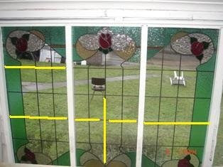
This image shows the starting of the weaving. A short lead covering only one quarry has been placed horizontally - although you can start with a short vertical, both are fine. The next lead is vertical and covers two of the quarries. As you can see here the two quarries at the right are ready for the longer horizontal to be placed.


You proceed in this fashion - alternating long and short leads throughout the grid area.


As you can see this builds up in a diagonal fashion with each vertical and horizontal line being interrupted after every second piece of glass.


If you look closely you can also see that these leads are being tucked. This is easier with leads of 7mm and greater than of 6mm and less.
This method of leading gets its name from the similarity to representations of weaving in illustrations where a broken line represents the thread or reed going under another. Its purpose is to avoid hinges and so strengthen the whole panel. This avoidance of hinges makes the turning of the panel during soldering and cementing much easier.

Of course, you must remember that the glass is the strongest part of the panel.

Monday, 27 July 2009

Direct or Trace cutting

Place the glass over the pattern and run the cutter along the pattern lines you see by looking through the glass. There's no need to draw lines on the glass. For translucent glass you may need a light box.

You should be aiming to cut glass efficiently and accurately. Trace cutting is the most efficient, as it completes in a single operation what other methods –such as drawing on the glass or making templates from the cartoon - take several steps to accomplish.

It is more accurate because each extra step required for other methods increases the possibility for error. The fewer times you copy the original pattern lines, the less likely you are to diverge from the original pattern lines.

It is very important to keep the cutter at right angles to the glass - as seen from side to side, not vertical.  This of course is true of all cutting.  It makes the cutting inaccurate, because the light is bent when coming through the glass much like water changes the apparent angle of sight into its depths.  Tilted cutters also have undesirable effects when breaking the glass.

Friday, 24 July 2009

Tinning brass vase caps

Tinning brass vase caps can help in obtaining a secure joint without long dwells at each joint that risk overheating the glass.

Heat your vase cap with a torch of one kind or another. You can heat until it becomes a dull red. The quickly brush or rub (with a cloth) flux onto the inside and outside of the rim of the vase cap. Apply a little solder to the fluxed area while everything is still hot. This will tin all the areas where the flux was placed.

This method will give a strong solder to solder joint that requires much less time when soldering the cap to the rest of the lamp shade.

Wednesday, 22 July 2009

Leaded Glass Reinforcements

I received a query recently about this subject. As the correspondence may be useful to a more general audience, I present an edited version here. (all the personal chat has been taken out!)

“I was wondering if I would be able to ask you a question regarding re-enforcements. In regards to the hollow lead with the bar running through or using Reforce with the brass molded through it. Which is better?”

The lead covered steel is stronger. It has the disadvantage that if it gets moisture into it, it will corrode. Steel expands when it corrodes. This leads to progressive destruction of the surrounding glass.

Brass is weaker, but does not have the same degree of expansion when corroding.

Steel is cheaper than brass.

These factors have to be taken into account when deciding on which to use. So I don’t have a definitive response for your situation.

Really any time you need to reinforce a panel, it is because it is too large to reliably support itself. Often this is because it is too tall or too wide. Big windows have always been built in sections, with each stacked upon top of the lower ones. There are saddle bars or ferramenta added to the window opening to strengthen the window.

It is important to note that in compression glass is much stronger than steel. It is when the glass is in tension that it is weaker. So what the reinforcement is doing is resisting any lateral movement. It is not holding the glass up. The glass can do that very well on its own. The glass is subject to lateral movement from wind pressures mostly. But in some situations as in doors, it is subject to inertial movements - the door closes and sometimes slams. In other installations there is vibration – such as sidelights. The re-enforcement is to counteract or reduce this movement.

In general, if the panel needs reinforcement, it is too large as a single panel, and needs to be built in several panels. Some people hate to have the line of the panel joints, but the eye generally ignores those straight lines (unless they are out of true horizontal or vertical).

Some questions you need to ask yourself about reinforcement are:
Do you really need to reinforce?
Must it be within the panel?
Can you use external support?
Why would two hinges be better than one?

Remember the reason for not having a hinge is because the glass is the strongest element in a leaded or copper foiled window. Therefore a window with complicated lines will be a stronger window as the glass interlocks. If you look at many older windows you will see a number of hinges, and the windows are still there. I attach an image of a stair window that has been in place for just under 100 years. It has a multiplicity of hinges. I am not saying don't concern yourself about hinges, but keep a sense of proportion.


Nowadays, I keep all my reinforcements to the surface of the panels, not inside. Also if you want to join panels in a large window, it is not essential that the join be horizontal or vertical. It could be in a wave, sinuous curve or in a stepped fashion. Your imagination is probably the limit here, not the material.


The enquirer then sent pictures with further information.

“These are the latest 3 panels I’ve made for my bungalow out the back. They measure 1100mm high by 500 wide approx. I’ve made them all with different reinforcement applications. I was told they would not need any but still wanted to strength them up.

“The middle you can see I broke the hinge line with two pieces of re-force and on the other two I’ve gone all the way through to the outer border. All other lead lines do not go more than 2 pieces of glass before they are crossed by another piece of lead to break up that hinge thing.

“Due to the size/design I’d appreciate your thoughts on what I’ve done being correct/overkill?”


The two outer panels are supported appropriately. I believe the right one is adequately reinforced, and the left is over reinforced, but there will be no harm. The middle one is not adequately reinforced. The broken horizontal reinforcement transfers the stresses to the middle. The vertical one also transfers the stresses to the middle, only a little higher.

For reinforcement to work, it needs to transfer the stresses to the sides/tops of the panel where they will be captured by the framing. Thus the reinforcement needs to be a continuous line. The strongest reinforcement will be across the shortest dimension of the opening.

The weaving of the lead lines described by you as “lead lines do not go more than 2 pieces of glass before they are crossed by another piece of lead to break up that hinge thing” is exactly the right thing to do in these panels.

In the case you are illustrating, there should be no problems for several generations at minimum and possibly for a century.


"I’ve also included one other piece I’ve designed and cut which is going to be installed in an internal wall inside a home. Its 800/800mm approx and due to it being kept out of the weather was wondering about what type of re-enforcement structure would suit?"


As this will be an internal panel, I suggest that the best reinforcement would be a toughened/tempered sheet of 4mm float glass installed behind the panel. This will provide support in case someone leans against it. Yes, there is a diagonal hinge at the trunk, but the strongest reinforcing for this would simply be a horizontal bar behind the panel, which would look ugly and I don't think you want anyway.


Friday, 17 July 2009

Positioning the Circle Cutter.

If you have a suction cup on the circle cutter, it will be easier to hold in place. But a three legged circle cutter is possible to keep in place too.

In both cases, one hand holds down the centre and the other operates the cutter. Make a test circle with no pressure to ensure before you start that the cutting bar will not bump into anything else on the bench. This also ensures that you have the circle to be cut placed appropriately on the glass.

To make the score start with the bar under your supporting arm and swing around to the other side of your arm until you hear the click or scratch indicating that you have come back to the start.

Monday, 13 July 2009

Lead and Copper Foil in the Same Panel


It is possible to combine copper foil in a leaded glass panel.

The copper foiled piece should be soldered before inserting it into the lead came. In this way the soldered together pieces become very like another piece of glass.

There are some special considerations, of course.

The copper foiled piece should be designed as though it were a single piece of glass and so can be accommodated into the surrounding pieces of glass. Copper foiled piece should not have severe undercuts which would make it difficult to insert into the surrounding glass. It may be necessary to incorporate a piece of the surrounding colour to make it fit into the panel.

The copper foiled piece should be finished with all the beads on both sides. If one side is left flat, it will collect water if on the outside, and catch on any cleaning processes whichever side it is on. However, the piece should be tinned only on the outer edges. This will ensure that the copper foiled piece will slip into the came.


The image below illustrates a copper foiled piece incorporated into a leaded panel.


This section of the panel shows the accommodation of the main leaded panel with the copper foiled piece with a line from a petal to a leaf. Otherwise, it was fitted as one piece.

Wednesday, 8 July 2009

Templates of openings, 6

When the opening is in stone, slight variations occur in the process of taking a template. The main difference is that the rebates are concealed. The rebates are slots into the stone. Thus, the template must slip into the slotted rebate. In these cases, the stiffer the material being used to take template, the better. Usually, thin plywood is the best material, as it has to be manipulated many times and in ways similar to the final panel.

Things are further complicated, as tracery is more common in stone than in timber framed openings. A complex opening shape may require two or more parts to enable the panel to be inserted. The taking of a template will help greatly in figuring out how the panel will be inserted into the opening.

Additionally, when the template is in position, you should mark the visible portion of the opening onto the template. Mark which is the inside and which the outside. Finally, mark on each template which side has the deeper slot as this will help in installation.

Monday, 6 July 2009

Templates of Openings, 5 – Irregular Openings

Irregular openings such as trefoils and other tracery need to have templates taken with consideration on how the final panel can be put into the opening.

In the cases where the whole of the rebate is exposed, it is normally possible to put the panel in as a single whole piece.

So, the template is taken as for any other opening. It is more complex and time consuming as there are so many more sides than in a simple rectangular or circular opening.

Saturday, 4 July 2009

Templates of openings, 4

Round headed openings can be considered as a special case of a circle.

The horizontal you must find is the shoulder of the window. This is the place from which the curve springs on each side. The opening is generally vertical up to this point and then begins the curve.

You need to make sure you have marked where this shoulder is on the template. You should indicate any reference points from the frame onto the template.

The join to the lower part of the window must be made obvious. Normally there will be an overlap between the lower rectangular template and this approximate half circle. You need to mark where this overlap occurs, if you do not fasten the two sheets together. This can be done by marking across the two sheets in a few places. This will enable you to join them exactly back at the studio.

Thursday, 2 July 2009

Templates of openings, 3 - Circles

Occasionally the window is circular and sometimes an oval. In both cases a template is important. The circle rarely is exact. Take the template in the normal way and then ensure you mark the verticals and horizontals for the opening. You often can use the jointing in the woodwork to help with these. Also mark any other reference points from the opening. Finally, mark which is the outside and which the inside.

This procedure will ensure that you will be able to fit the panel into the opening.